












First, let us clarify the issue this article addresses: if a water well drilling crew needs to move continuously between multiple sites in a year, drilling a few wells at each site before relocating, then being familiar with the equipment specification sheet does not directly answer whether this equipment can be arranged within our pace of frequent moves. The conditions that frequent moves impose on equipment are not entirely on the same level as the conditions during drilling operations.
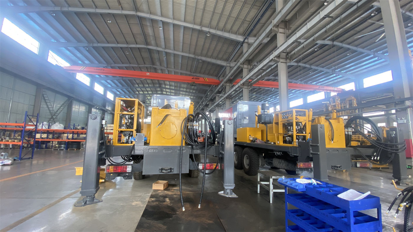
This article uses the publicly available information on the WR400S as a reference: 400 m class, telescopic mast, crawler chassis, supports direct operation with 6 m drill pipes and 6 m casing, overall weight about 9.8 T, dimensions about 6.26 × 1.85 × 2.43 m. Based on these verified details, the items that need to be decided before mobilization are listed in order.
The first thing to decide before mobilization is "how long the drill pipes should be"
The choice of drill pipe length affects several subsequent arrangements: the number of pipe connections, auxiliary time, drill tool handling method, and how to secure the load during transport. The WR400S information states that it supports direct operation with 6 m drill pipes, with recommended drill pipe diameters of 89 / 102 mm. The information also notes that long drill pipes can reduce the number of pipe connections in 300–400 m class water wells, lowering auxiliary time and manual handling frequency.
It should be noted that the benefit of 6 m drill pipes and the mast form are not the same thing. The telescopic mast addresses the transport envelope issue, while the 6 m drill pipe addresses the number of in-hole connections and disconnections. The two are linked end-to-end in the same efficiency chain, but they should be decided separately before mobilization.
Define transport state and working state separately
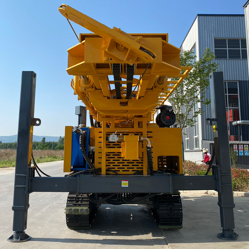
The S in WR400S corresponds to the telescopic mast. The information states: in transport state, the mast can shorten the overall transport envelope; in working state, it continues to support direct construction with 6 m drill pipes or 6 m casing. The direct implication of this for mobilization arrangements is that during loading, road passage, and site turning, the equipment faces a relatively short mast envelope; after reaching the hole position, it is then extended into working state.
Several items that should be documented or briefed before mobilization follow from this:
- Whether the mast is in the safe transport state referred to in the information during moves, and how the locking structure is handled;
- Where the equipment tie-down points are selected after loading, and whether drill pipes are secured separately;
- How much clearance and what ground conditions are needed to extend into working state after reaching a new hole position;
- The telescopic mast guide rails, hydraulic cylinders, pins, and locking structure are included in routine inspections.
The last item is a separately listed inspection point in the information. Frequent moves mean this structure operates many times, so inspection frequency cannot be based solely on a fixed calendar schedule.
Overall weight and dimensions constrain loading and passage
The WR400S has an overall weight of about 9.8 T, dimensions of about 6.26 × 1.85 × 2.43 m, a travel speed of about 2.5 km/h, and a maximum climbing angle reference of 21° as given in the information. These values do not all need to be memorized before mobilization, but two types of arrangements must be defined against them:
| Item to decide | Corresponding information | Items to verify |
|---|---|---|
| Flatbed trailer matching and loading method | About 9.8 T, dimensions about 6.26×1.85×2.43 m | Trailer bed height, tie-down points, securing plan |
| Village roads, field roads, site access route | Travel speed about 2.5 km/h, climbing reference 21° | Road width, bridge and culvert weight limits, turning radius, wet or slippery conditions |
| Equipment positioning at the hole site | Crawler chassis, hydraulic outrigger stroke 1.6 m | Ground bearing capacity, whether soft soil requires mats |
The third column in the table contains items not covered in the information but that must be addressed in mobilization arrangements. Without these, the values in the previous column only describe the equipment itself, not whether it can reach the hole position you intend to drill.
Impact of move frequency on accessory selection
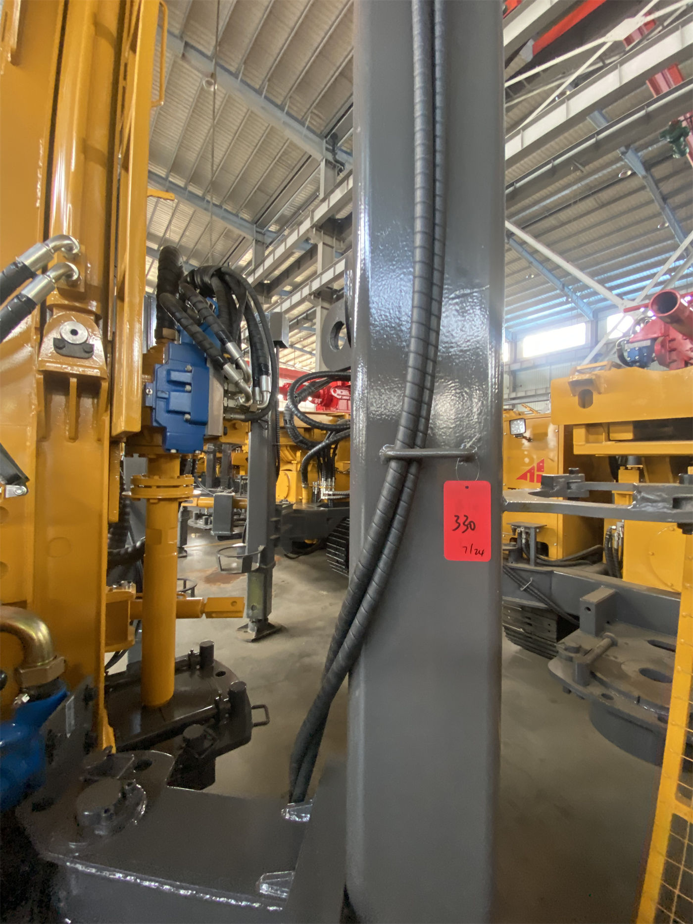
The WR400S can be equipped with mud pumps, centrifugal pumps, generators, and foam pumps. The guidance in the information is: loose formation projects need a mud system more, hard rock projects focus on configuring air compressors and DTH hammers, and formations with severe air loss may use foam assistance. For crews that move frequently, this configuration has an additional constraint—the more concentrated the accessories, the longer the item list for loading and unloading each time.
Therefore, accessory selection should not be based solely on the optimal process for a single well; transport organization when changing sites should also be considered. The information does not provide specific dimensions and weights for each accessory, so this part needs to be confirmed separately with the manufacturer when deciding on the procurement configuration.
Items to coordinate with in-hole operations before and after moves
Moves are not just a transport issue; they also relate to whether the next well can start drilling immediately. The information related to this transition includes:
- Rotary system maximum torque 8000 / 4000 N·m, corresponding to maximum rotation speeds 75 / 150 r/min, with the two operating conditions switched according to drill tools, rock formation, and cuttings return status;
- Lifting force 22 T, axial pressure 4 T;
- Lifting and feed speeds are 29 m/min and 56 m/min respectively, used for power head return, drill pipe handling, and non-drilling actions;
- Auxiliary winch lifting force 1.5 T, used for moving DTH hammers, drill pipes, casing tools, and site accessories;
- DTH hammer recommended working air pressure 1.2–3.5 MPa, air consumption 16–55 m³/min;
- Power source is a 92 kW Yuchai engine, providing power for rotation, feed, crawler travel, and auxiliary hydraulic systems.
These values themselves do not change due to frequent moves, but they determine the preparation content for restarting drilling after changing hole positions: how drill tools are transferred from the previous hole, whether the air compressor displacement is sufficient, and whether non-drilling actions such as power head return can reduce auxiliary time. The information does not provide specific durations between different sites, so it should not be used to estimate efficiency improvement margins.
Scope of application and parts still to be confirmed
The information states that the WR400S has a maximum drilling depth of 400 m and a drilling diameter of 105–325 mm, covering scenarios such as farmland irrigation, rural water supply, aquaculture, and industrial construction water wells, and supports mud drilling and DTH hammer drilling. These are descriptions of the applicable scope in the information, not a basis for judging the well completion results of a specific project; actual completed well depth should still be determined according to hydrogeological conditions.
The following items are not provided in the publicly available information and need to be verified separately before deciding on equipment:
- The width, load-bearing capacity, slope, and turning conditions of each road segment on the move route, and how they match the approximately 6.26 m length and approximately 9.8 T weight;
- The operation time and clearance required to extend and retract the telescopic mast, and how many people are needed to complete it;
- The total transport volume and vehicle arrangements when all optional accessories travel together;
- Whether the foundation at the new hole position requires special treatment, and the form and dimensions of mats.
Summarizing the items to decide before mobilization
For water well drilling crews that move frequently, the items to decide before mobilization can be divided into three layers: the first layer is in-hole process, including drill pipe length, drill pipe diameter, target well depth, and hole diameter; the second layer is move arrangements, including switching the mast between transport state and working state, loading tie-down, and site access route; the third layer is accessories and inspection, including the accessory travel list and inspection frequency for telescopic mast-related structures. The publicly available information on the WR400S provides clear basis for the first layer and part of the second layer—the telescopic mast improves the transport envelope, the 6 m drill pipe reduces the number of pipe connections, and the overall weight of about 9.8 T and dimensions of about 6.26 × 1.85 × 2.43 m constrain loading and passage. The accessory dimensions, specific road conditions, and extension time involved in the third layer still need to be based on site surveys and manufacturer confirmation; the information itself does not support direct conclusions.