












When looking at a water well drilling rig specification table, the rotary system is often written as two adjacent values, for example maximum torque 8000/4000 N·m, corresponding to maximum rotation speeds of 75/150 r/min. The easiest way to read the relationship before and after the slash is to treat it as a two-speed transmission: engage high speed for fast, low speed for power. But water well drilling is not shifting gears on the road; these two values correspond to rotary output under different downhole resistance conditions, and the basis for selection comes from hole diameter, rock formation, and cuttings return conditions, not driving habits.
What Exactly the Two Sides of the Slash Describe
Taking the publicly available information for the WR400QS on this site as an example, the rotary system is written as two speed values. The common convention for this type of notation is: before the slash is the high-torque, low-speed first gear, and after the slash is the lower-torque, higher-speed gear. 8000 N·m with 75 r/min, 4000 N·m with 150 r/min. What they describe is not two speed buttons, but the capability boundaries of a machine in two rotary output ranges.
A vehicle transmission's gears correspond to a combination of vehicle speed and traction, and the basis for shifting is mainly road surface and load; the shifting process itself does not change the work object. Drilling is different: when switching rotary output, the downhole condition has already changed, with the drilling tools, rock cuttings, and borehole wall acting together, and the timing of the switch is tied to the target hole section.
Which Hole Sections the Low-Speed High-Torque Gear Targets
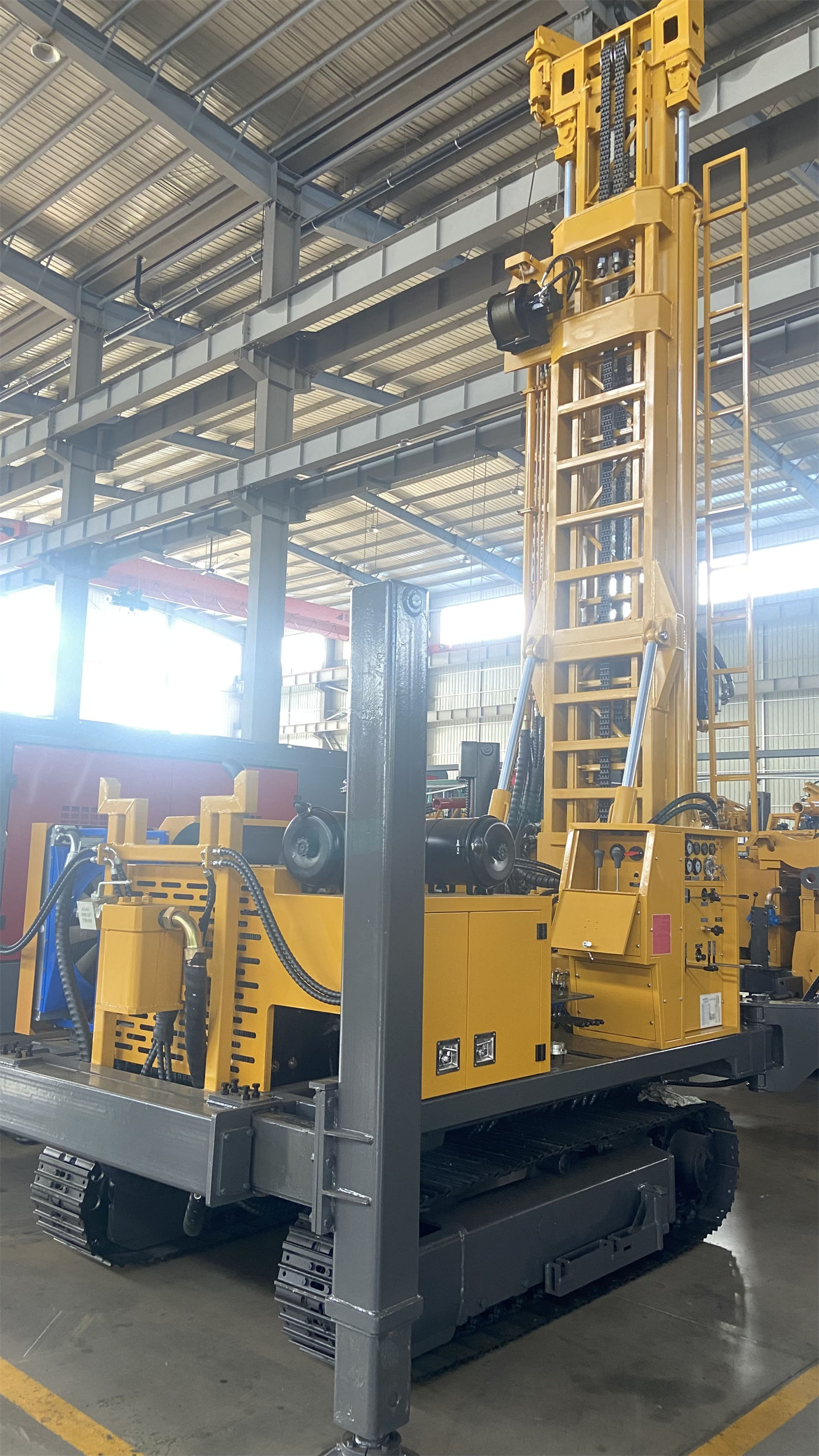
The 8000 N·m, 75 r/min gear, according to the specification, is more suitable for large-diameter, hard rock, and high-load conditions. These conditions can be understood from several directions:
- The larger the hole diameter, the larger the contact area of the drill bit at the bottom, and the rotary resistance rises accordingly, requiring greater torque to maintain rotation.
- In intact hard rock, the drill bit or DTH hammer cuts and impacts the rock mass, and the downhole reaction torque is high; too high a rotation speed is not conducive to drilling tool stability and cuttings return.
- As hole depth increases, the self-weight of the drill pipe and borehole wall friction add up, and the rotary system needs sufficient torque margin.
This gear does not pursue rotation speed per unit time, but ensures that rotation is not stalled by downhole resistance. In hard rock, a lower rotation speed also facilitates timely removal of rock cuttings at the bottom by air flow or mud, reducing regrinding.
Hole Section Conditions Corresponding to the Higher-Speed Gear
The 4000 N·m, 150 r/min gear corresponds to a drilling stage with relatively lower resistance. The WR400QS specification describes it as "a drilling stage with relatively lower resistance" and does not list a fixed formation checklist. It can be understood in this direction: when the hole diameter is relatively small, rock strength is not high, and downhole friction is controllable, using a higher rotation speed increases the number of rotations per unit time, and the number of drill bit cutting actions rises accordingly.
It should be noted that a higher rotation speed does not equal faster hole completion. Increasing rotation speed simultaneously changes the downhole flow field, drilling tool vibration, and cuttings return state. If downhole rock cuttings removal cannot keep up, a high rotation speed instead increases regrinding. The applicable conditions for this gear should be considered together with cuttings return and air or mud supply conditions.
In the Same Well, the Two Gears Correspond to Different Hole Sections
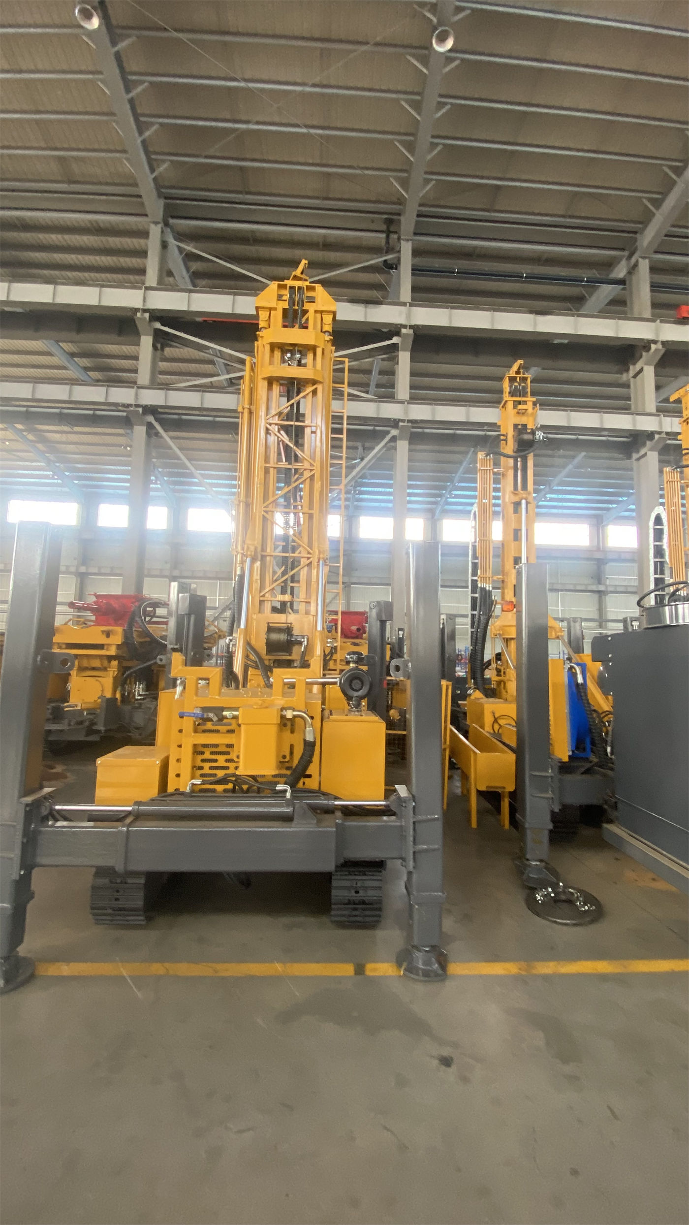
When the two gears are understood as a transmission, it is easy to assume they are fixed settings before construction. In reality, the same 400-meter-class water well will pass through different hole sections from top to bottom: the upper overburden may be soil, clay, or sand, then weathered rock and fracture zones, and then intact rock. The WR400QS specification supports DTH hammer drilling and also mud rotary drilling, and the drilling method itself may change by section.
| Hole Section Characteristics | Rotary Output Tendency | Conditions to Also Check |
|---|---|---|
| Large diameter, intact hard rock | High torque, low speed | DTH hammer air pressure, bit condition, cuttings return |
| Relatively low resistance stage | Lower torque, higher speed | Rock cuttings removal, borehole wall stability |
| Fractured zone, fissured formation | Do not blindly increase output | Signs of block falling, air leakage, hole shrinkage |
The third row in the table deserves a separate mention. The WR400QS specification indicates that fractured zones may cause block falling, air leakage, and drill sticking; at this time, overly fast advancement should be reduced and continuous hole cleaning maintained, rather than simply relying on higher torque or greater lifting force to force through. This shows that the two rotary output gears are not a solution to all downhole resistances.
What the Torque Values Themselves Cannot Define
8000/4000 N·m written in the specification can indicate the upper limits of this machine in two output gears. It cannot directly answer the following questions:
- How much torque is required for a specific hole diameter—this also depends on rock strength, bit type, and drilling tool combination.
- Which gear should be used for a specific rock formation—the specification gives applicable directions, not a formation comparison table.
- How to transition and switch between the two gears—this is an on-site operation and process issue, and the specification does not provide switching criteria.
- Whether the torque margin is sufficient to handle drill sticking—when encountering drill sticking, hole shrinkage, or borehole wall block falling, the specification recommends prioritizing hole cleaning and adjusting the process, rather than relying on maximum lifting force to pull hard.
In other words, this set of values is one of the inputs for judging the machine's capability boundaries, not a conclusion that can be directly applied to a specific hole section.
Why This Set of Values Should Be Read Together with Each System
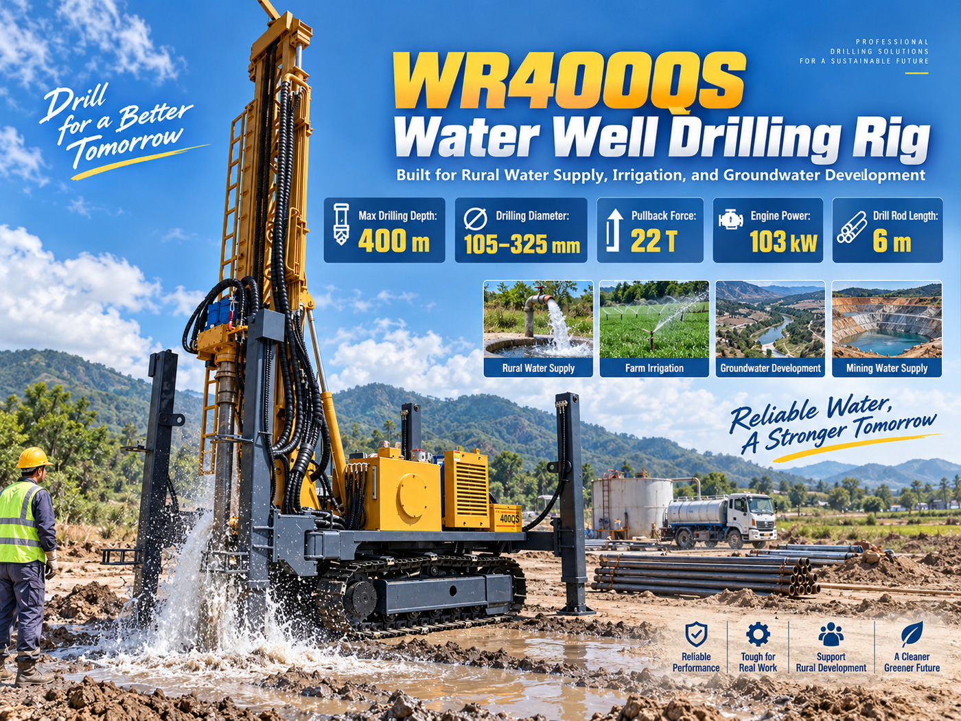
Looking at dual-condition torque alone makes it easy to overestimate or underestimate a machine. The related parameters given in the WR400QS specification include: lifting force 22 T, axial pressure 4 T, fast lifting speed 29 m/min, maximum drilling depth 400 m, drilling diameter 105–325 mm, recommended drill pipe diameter 89/102 mm, working air pressure 1.2–3.5 MPa, air consumption 16–55 m³/min, and overall weight about 8.6 T.
Rotary torque has reference relationships with these parameters: hole diameter determines rotary resistance and also determines the space required for well completion; hole depth determines the self-weight of the drill string, which in turn affects the lifting force margin; during DTH hammer drilling, whether the air compressor displacement is sufficient is often more important than whether a certain pressure value is reached. Looking at torque in isolation loses its place in the entire chain.
Suggested On-Site Judgment Sequence
According to the sequence supported by the specification, putting dual-condition torque back into construction judgment can proceed as follows:
- First determine the target well depth, completed well diameter, and well casing structure; these determine the load magnitude.
- Then determine the drilling method for each hole section according to the formation combination, whether mud rotary or DTH hammer.
- Then check whether the rotary output covers the resistance state of the corresponding hole section.
- At the same time, confirm whether the lifting force, axial pressure, air pressure, and air consumption match the selected drilling tools and air compressor.
- Before entering the site, separately verify the machine weight, overall dimensions, and on-site road and ground bearing capacity conditions.
In this sequence, dual-condition torque appears in the third step; it answers "whether the rotary can drive this hole section," not "whether this machine is fast."
Parts Still Needing Confirmation Beyond the Specification
The publicly available WR400QS specification gives the two gear values and applicable directions of the rotary system, but before a specific project is implemented, several types of information still need to be confirmed at the project or manufacturer level:
- Local hydrogeological conditions determine the final well depth; the capability upper limit of a 400-meter-class machine does not equal the target well depth.
- Actual drilling efficiency is affected by formation, drill bit, DTH hammer, and air compressor; the specification has noted that on-site working conditions should prevail.
- The correspondence between drill pipe and casing specifications and machine configuration needs to be confirmed item by item in conjunction with the completed well structure.
- Optional configurations such as mud pumps, centrifugal pumps, generators, and foam pumps are selected according to project formation conditions and are not part of the fixed machine configuration.
The problem with understanding dual-condition torque as a two-speed transmission is that it treats a capability boundary as an operating option. A reading closer to the original meaning of the specification is: these two values respectively mark the upper limits of the rotary system under two types of downhole resistance states, and the actual basis for selection comes from hole diameter, rock formation, drilling tools, and cuttings return, not from the feel of shifting gears.