












"My well is about two hundred meters—can I just choose a 200-meter drilling rig?" This is the most common way the question is asked in 200-meter-class water well projects. It compresses rig selection into a single numerical comparison, but whether a 200-meter-class machine can drill that well depends on a set of conditions, not just one: how deep the well is, what size well casing is needed, how thick the upper overburden is, where the aquifer is located, how the rock formation is drilled, and whether the equipment can reach the well site and stand stably. Using the published information of the WR200SE as a reference, this article breaks down the operating conditions that truly need attention behind those two hundred meters, explaining which parameters correspond to which requirements and which must be separately addressed on site.
Order for breaking down operating conditions
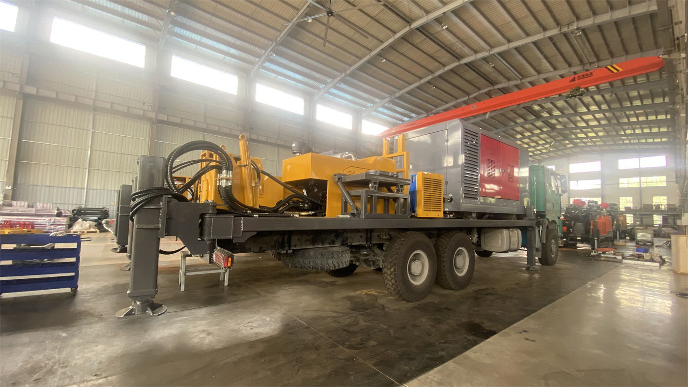
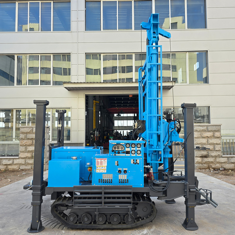
First, a clarification: all discussion below is based on the published specifications of the WR200SE. Values for other models cannot be directly applied. This machine is a 200 m-class crawler water well drilling rig with a telescopic mast, Yuchai 58 kW power, drilling diameter 140–254 mm, drill rod diameter 76/89 mm, drill rod length 1.5/2.0/3.0 m, rotary torque 3400–4700 N·m, rotary speed 45–70 r/min, lifting force 13 T, fast lifting speed 30 m/min, fast feed speed 60 m/min, single feed length 3.3 m, high outrigger stroke 1.4 m, reference working pressure 1.7–2.5 MPa, air consumption 17–31 m³/min, overall weight about 4.7 T, travel speed about 2.5 km/h, and maximum gradeability reference 30°.
These values do not need to be memorized; their purpose is to answer the next six questions. Note that equipment parameters can only answer questions on the equipment side. Geological questions must be answered by the project's own survey data.
Item 1: The margin left by the number 200 meters
200 m is the maximum drilling depth. A well with a completed depth close to 200 m and a well expected to encounter water at 150 m do not place the same demands on the same machine. The information states clearly: the actual completed well depth still needs to be determined in combination with local hydrogeology, aquifer location, borehole diameter, drilling tools, and construction process. In other words, 200 m is the upper limit of equipment capability, not the water-finding depth.
There is another statement in the information that can be quoted directly: for rural areas with relatively deep groundwater levels, farmland irrigation areas, and hilly terrain, 200 m-class equipment has a greater water-finding depth margin than 120-meter-class models. This means that when there is uncertainty in water level judgment, a 200 m-class rig leaves more room for adjustment than a 120-meter-class one—not that 200 m will necessarily drill better than 150 m. If regional hydrological data has already defined the aquifer location within a certain interval, then judging the class by target well depth plus a reasonable margin is more conservative than judging by the maximum nominal value.
There is another misreading to avoid: the information also states that during construction, the well location should be reasonably determined based on local groundwater data, avoiding reliance solely on expanding drilling depth to compensate for siting errors. Drilling depth does not replace siting judgment.
Item 2: Well casing and pump corresponding to the borehole diameter range
The WR200SE's drilling diameter range is 140–254 mm. This range covers the size requirements of common water well casing and submersible pump configurations, but the specific diameter chosen does not depend on the equipment's preferred value; it depends on the completed well structure: casing outer diameter, screen length, gravel pack thickness, submersible pump outer diameter, and target water yield.
There is a judgment in the information that can be used directly as a selection basis: for agricultural wells requiring long-term pumping, the well diameter, screen, and pump type should be determined before construction based on expected water yield, rather than simply pursuing a larger borehole diameter. The larger the borehole diameter, the higher the demand for rotation, cuttings removal, and air volume. On a 200 m-class machine, setting the borehole diameter at the minimum reasonable value that satisfies casing and pump requirements is more favorable for load control during drilling. This point has no corresponding field in the parameter table and needs to be confirmed during the project design stage.
Item 3: Lifting force and rotary torque correspond to the process
The value of 13 T lifting force governs tripping, drill rod handling, and some casing operations—not hole depth. The deeper the hole, the longer the drill string, and the greater the friction in the hole, the more obvious the load that lifting force must bear. The WR200SE's 13 T is a normal configuration in the 200 m class, but the information also states: when encountering stuck drill, hole wall narrowing, or abnormal return water, the formation and downhole conditions should first be assessed, then the problem solved through hole cleaning, pulling out to inspect, or casing treatment, avoiding simply relying on large lifting force to pull the drill tools forcefully. This statement is more significant for judgment approach than for parameters.
Rotary torque 3400–4700 N·m, combined with rotary speed 45–70 r/min, corresponds in the information to the applicable range of weathered rock and intact rock formations, and can be used with common DTH hammers for pneumatic drilling. The information also notes that during drilling, rotation and feed should be adjusted according to rock hardness and cuttings removal conditions; long-term rigid construction with a single set of parameters is not recommended. Therefore, before procurement or commencement, the items to confirm are: whether the target formation is mainly soil, sand-gravel, or rock; which DTH hammer and bit will be used for the rock section; and what the maximum borehole diameter is. If these three items are not clearly confirmed, the torque value alone cannot lead to a conclusion.
Item 4: Air compressor matching is the most error-prone item
Reference working pressure 1.7–2.5 MPa, air consumption 17–31 m³/min. These two values are the machine's requirements for the air compressor, not the air compressor's own capability. There is a conditional statement in the information worth quoting separately: different borehole diameters, DTH hammers, and rock formations have greatly differing requirements for the air compressor; for example, when borehole diameter increases, rock becomes harder, or altitude rises, a more sufficient displacement is usually required. Insufficient air compressor matching directly affects impact frequency, cuttings removal, and drilling efficiency.
The way this item causes problems in actual procurement is very specific: increasing borehole diameter from 140 mm to 254 mm, entering harder rock such as granite, or operating at higher altitude—all three situations push the requirement toward the upper end of the 17–31 m³/min range or even beyond. Therefore, when verifying the air compressor configuration with the manufacturer, borehole diameter, DTH hammer model, rock hardness, and operating altitude should all be stated together, rather than reporting only a drilling depth.
Item 5: Formation segmentation determines how the process proceeds
The published information of the WR200SE gives relatively clear treatment directions by formation type. This part is more important for judging whether the equipment is suitable than the parameters:
- Soil, clay, sand-gravel, and loose overburden: the information states that directly using a DTH hammer is not necessarily the best solution. Loose overburden is prone to hole collapse, buried drill tools, and borehole enlargement. The upper hole section should first be treated with casing, mud, or other hole-stabilizing methods before entering stable rock to continue drilling.
- Weathered rock: usually faster penetration, but hole wall stability may be poor. Whether to follow up with casing should be decided based on falling blocks and hole narrowing.
- Relatively intact rock such as limestone, sandstone, and granite: suitable DTH hammers and bits can be used for pneumatic drilling, with focus on controlling the coordination of air volume, rotation, and feed.
- Fractured zones and fissured formations: may cause air leakage, falling blocks, and stuck drill. Excessive feed should be reduced, continuous hole cleaning maintained, and changes in downhole air pressure and cuttings return observed; if the fractured zone is thick, follow-up casing or casing methods may be considered.
- Aquifer and strong water inflow conditions: water inflow changes the cuttings removal state in the hole and the working conditions of the DTH hammer. Air compressor supply and hole cleaning methods should be adjusted according to actual water yield, aquifer depth recorded promptly, and well casing, screen, and water-stop structures reasonably arranged before well completion.
Looking at this content together with the previous parameters: whether a 200 m-class machine can be used depends largely on how thick the upper loose layer is and how much fractured zone is present. If the overburden is very deep and the fractured zone is very thick, casing and hole-stabilizing procedures will consume a considerable amount of work. This workload needs to be separately prepared in terms of schedule and supporting materials, rather than being covered by drilling depth parameters.
Item 6: Site conditions for access and standing stability
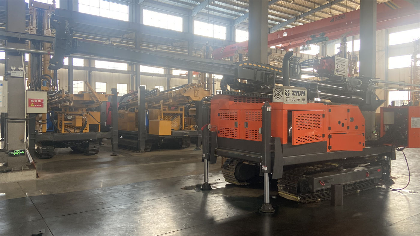
Crawler chassis, travel speed about 2.5 km/h, maximum gradeability reference 30°, overall weight about 4.7 T, dimensions about 3950 × 1750 × 2250 mm, high outrigger stroke 1.4 m. Together, these constrain whether the equipment can reach the hole location and whether it can stand stably once there.
The information states that the crawler structure is suitable for rural roads, farmland, gravel sites, and mildly uneven ground; when moving on slopes, the center of gravity should be lowered, the mast retracted, and ground adhesion conditions confirmed. Actual safe gradeability should be judged according to site conditions. The 1.4 m high outriggers are used for support and leveling on uneven ground. Before drilling begins, the chassis and outriggers should be ensured to bear force stably, with additional pads if necessary, to avoid tower tilting and hole position deviation caused by sinking on soft ground.
This section corresponds to what must be confirmed before entry: the distance between the hole location and the road, whether the road width can accommodate the entire machine, and whether the site has enough space to support the 1.4 m outriggers. The information provides a loading width field but the main text does not elaborate on it, so matching transport vehicles needs to be separately confirmed with the manufacturer during procurement. This article does not infer it.
What the telescopic mast and drill rod length change in the operation
The telescopic mast has a single feed length of 3.3 m and can be equipped with 1.5 m, 2.0 m, and 3.0 m drill rods. Together, these two sets of values determine the rod connection frequency: with a single feed of 3.3 m, using 3.0 m drill rods basically allows one rod to be fed continuously, while using 1.5 m drill rods requires more connections and disconnections. The information describes the value of the telescopic mast as greater flexibility in transport and site adaptation, while also providing good working space for drill rod handling and continuous drilling under normal operating conditions. This is a structural description on the equipment side. How much auxiliary time can actually be saved depends on drill rod selection and on-site operation. The information does not provide corresponding data, and this article does not calculate it.
Regarding supporting selections, the information lists 76 mm or 89 mm drill rods, DTH hammers, bits, casing tools, air compressors, air hoses, oil misters, and foam equipment, and states that supporting equipment should be combined according to target hole depth, borehole diameter, rock formation, and construction method. It is not recommended to configure all items only according to maximum parameters.
Items to be separately addressed before and after commencement
The daily inspection items given in the information include: hydraulic lines, rotary head, winch, crawler, mast, and drill rod connections; air compressor and high-pressure air hoses should have joints and safety devices checked; during construction, continuously observe air pressure, cuttings return, return water, and equipment temperature; after completion, clean mud and dust and inspect wearing drill tools. These are maintenance items on the equipment side and cannot replace on-site geological judgment.
The information finally states the boundary: due to differences in actual geological conditions, downhole tools, drilling angle, and operating methods, the final drilling efficiency, drilling depth, and well completion effect should be based on on-site working conditions. The reference drilling efficiency range of 10–35 m/h is also based on this premise. It is a range value and cannot be used to schedule work by a single number.
Gathering the six conditions into one judgment sequence
The selection of a 200-meter-class water well drilling rig can proceed in this order: first determine the target well depth and water-finding margin, then determine well casing and borehole diameter, then determine the process and casing requirements by formation segmentation, use borehole diameter, rock formation, and altitude to verify air compressor displacement, and finally verify access roads, hole location space, and outrigger support conditions. After these six items are confirmed, compare them against the published parameters of the WR200SE to see which conditions fall within the equipment range and which require additional configuration or a different model.
If one of these conditions cannot currently be determined—for example, aquifer location, overburden thickness, or maximum borehole diameter is not yet decided—then what can be done at this stage is conditional judgment: first estimate the required borehole diameter and air volume using conservative assumptions, then confirm the corresponding configuration with the manufacturer. Before these conditions are clearly verified, deciding on a model based only on the number "200 meters" is not enough to judge whether this machine is suitable.