












When browsing the specification table of a small water well drilling rig, power and lifting force often appear close together: one row lists engine power, another lists lifting force. The numbers stand alone, easily taken as the most direct comparison between two machines—higher power means more strength, higher lifting force means it can lift more. But these two values constrain different stages of the drilling process. Reading them separately is necessary to judge whether a small model matches the well at hand.
Below, using the publicly available specifications of the WR180E from this site as a reference, these two rows are placed back into its operational chain. The model's specifications state: maximum drilling depth 180 m, drilling diameter 90–230 mm, 28 HP Changchai diesel engine, 16 T lifting force, 1.5 m mast, total weight 1.8 T, rotation speed 40–70 rpm, compatible with 50 / 60 / 76 mm drill pipes, and drill pipe lengths of 1.5 m and 2.0 m.
Where These Two Rows Fall in the Specifications
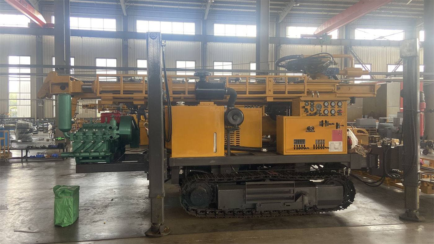
The power row describes the overall energy source of the machine. The WR180E specifications state that the 28 HP Changchai diesel engine provides power for the hydraulic system, rotation, and crawler travel. In other words, this single value covers three different things: driving the drill tool rotation, driving crawler movement, and supplying pressure oil to the hydraulic circuit. It does not independently correspond to "what rock formations it can drill through."
The lifting force row describes how much pulling force the winch or feed system can exert. The specifications state 16 T, used for routine drill pipe tripping, drill tool recovery, and handling some downhole tools. It constrains the stages of tripping and downhole tool recovery, not the rotational output during drilling.
There is no direct conversion relationship between the two rows. Power cannot be used to calculate lifting force, and lifting force cannot be used to infer engine power; each corresponds to different executing components.
What 28 HP Means in a 1.8 T Machine
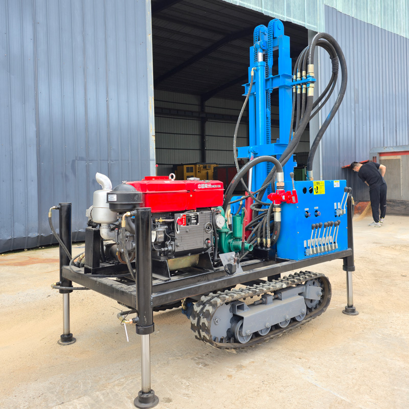
The WR180E has a total weight of approximately 1.8 T, equipped with a 1.5 m mast, 40–70 rpm rotation, and 90–230 mm hole diameter. Placing 28 HP within this configuration, its positioning is as an economical and practical compact equipment power source, rather than a high-power solution pursuing large-diameter or deep-hole continuous drilling.
The specifications also include a set of working parameters matched to this power: working pressure 1.7–3.0 MPa, travel speed 2.5 km/h. These values together define the machine's working rhythm—rotation speed range, hydraulic pressure range, and travel speed are interrelated, and power output is used within this range.
What really needs attention on site is under what conditions this power approaches its limits. The specifications state: if the project is mainly complete high-hardness rock formations, or long-term operation near maximum drilling depth, the drill tools, power, and equipment level should be re-evaluated for suitability. This statement clarifies the power's applicable scope—it serves routine shallow to medium-depth water well construction, not long-term full-load drilling in hard rock.
Which Procedures the 16 T Lifting Force Corresponds To
Tripping is the most frequently repeated action in water well construction. The deeper the well, the longer the drill string, and the greater the weight that needs to be lifted; different drill pipe diameters and lengths mean different weights per pipe. The WR180E supports three drill pipe diameters (50 / 60 / 76 mm) and two lengths (1.5 m and 2.0 m). When different specifications are selected, the total drill string weight at the same hole depth varies.
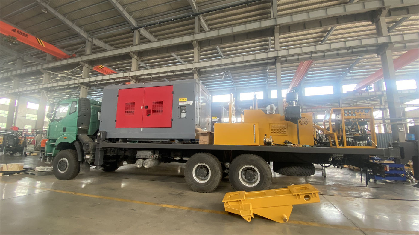
The 16 T lifting force at the 180 m drilling depth level is the matched value given in the specifications. But this does not mean "any downhole situation can be lifted." There is a statement in the specifications that must be taken seriously at the construction level: if abnormal tripping resistance, hole wall shrinkage, or poor cuttings removal occurs, the formation and downhole conditions should be assessed first, and it is not recommended to rely solely on maximum lifting force to force a solution.
This statement also explains how to use the lifting force row: it is a capability reference under normal procedures, not a fallback for handling downhole anomalies. When resistance is encountered, the basis for action is formation assessment and cuttings removal status, not using lifting force to its limit.
Placing Both Rows Back into the Same Operational Chain
In shallow to medium-depth water well construction, the stages each row is responsible for can be mapped as follows:
| Operational Stage | Main Values Involved | Specification Notes |
|---|---|---|
| Drill tool rotation | 28 HP power, 40–70 rpm rotation speed | Power provides energy for hydraulic system, rotation, and crawler travel |
| Tripping | 16 T lifting force, drill pipe diameter and length | Used for routine drill pipe tripping, drill tool recovery, and handling some downhole tools |
| Downhole anomaly handling | Not solely relying on lifting force | Formation and downhole conditions should be assessed first; forcing is not recommended |
This table aims to show: the power value affects whether the drill tool can rotate as required and work within the given speed range; the lifting force affects whether the drill string can be normally raised and lowered. Both work together continuously in the same hole, but are not defined by the same value.
Common Overinterpretations When Reading Small Rig Specifications
- Using power to infer drillable rock hardness. The specifications do not provide a power applicability range divided by rock hardness; they only state that equipment level should be re-evaluated when complete high-hardness rock formations are predominant.
- Using lifting force to infer maximum completed well depth. 16 T is the matched value for this model, and 180 m maximum drilling depth appears alongside it in the specifications, but actual completed well depth still needs to be determined based on local groundwater level, aquifer position, hole diameter, and construction technique.
- Treating the two rows as the entirety of the machine's capability. This machine also has parameters such as 1.5 m mast height, 1.8 T total weight, and dimensions of approximately 3000 × 1300 × 1700 mm, which respectively constrain site access, transport loading/unloading, and rod connection frequency.
- Ignoring the impact of drill pipe specifications on the number of procedures. A 1.5 m mast means drill pipe replacement frequency will be higher than long-stroke models, a direct result of this equipment's positioning toward flexibility and economy.
Conditions Not Covered in the Specifications That Require Separate Confirmation
The WR180E specifications give a drilling diameter range of 90–230 mm, but do not provide the correspondence between specific well casing dimensions, submersible pump specifications, and expected water yield; these need to be determined according to the actual project.
The specifications state that this model can be used for rural water supply, farmland irrigation, orchards, farms, and other scenarios, and also note that soil layers, clay, sand layers, and gravel layers may experience hole collapse, shrinkage, and drill burial, and that operating parameters should be adjusted for weathered rock and alternating soft-hard formations. However, which drill tools to select for each formation and which hole stabilization method to use are not specifically stipulated in the specifications and need to be judged based on site conditions.
In addition, the specifications mention that before starting work, the crawler, mast, hydraulic lines, drill pipe connections, and power system should be checked; during construction, rotation resistance, cuttings removal, and equipment temperature should be continuously observed; and during relocation and transport, the equipment should be properly secured. These are equipment usage requirements, and specific practices should refer to the accompanying documentation and on-site management arrangements.
Returning to the initial question: in small rig specifications, the power and lifting force rows are read differently. The power row looks at which systems it covers and within what operating range it is used; the lifting force row looks at which procedures it corresponds to and under what premises it should not be relied upon. Placing both rows back into the operational chain, and viewing them together with drilling depth, hole diameter, mast, and drill pipe specifications, forms the basis for judging whether a small water well drilling rig matches a given project.