












In discussions of deep-hole project plans, the drilling depth figure is often the first thing put on the table: 1000 m class or 1500 m class. It seems that as long as the number is increased, more wells can be covered. But in an actual borehole, drilling depth is only a rated upper limit. It does not itself create capability, nor does it indicate under what conditions the rig can complete the well. Taking the publicly available WR1500S data as an example, the maximum drilling depth of 1500 m is one line in the specification table, while the same table also includes values such as 80 T lifting force, 31000/15500 N·m rotary torque, recommended air pressure of 1.65–8 MPa, and 28 T overall weight. The relationships among these values determine whether a deep hole can be completed as planned.
The deeper the hole, the first thing pushed up is the weight of the drill string itself
The first change brought by increased hole depth is not insufficient equipment capability, but that the things that need to be lifted and lowered become heavier. With 9.6 m drill pipes and recommended diameters of 114/127 mm, as these pipes are connected one by one, their self-weight accumulates with hole depth. The 80 T lifting force and 16 T axial pressure given for the WR1500S lie on this chain: lifting force corresponds to tripping, drill tool recovery, and some large-diameter casing operations, while axial pressure corresponds to the component applied to the hole bottom during drilling.
There is an easily misread point here. 80 T is not “the amount used in every well”; it is a margin that varies with hole depth, drill string specifications, borehole wall friction, and local resistance. As hole depth increases, drill string self-weight, borehole wall friction, casing weight, and possible local sticking all add up. When the lifting force margin is insufficient, tripping will first become difficult. Conversely, a large lifting force rating does not mean abnormal resistance can be pulled through by force—the principle indicated in the data is to clean the hole first, lift slowly, and judge the downhole condition.
Torque has two ranges, corresponding to different hole sections rather than two speeds
The rotary system of the WR1500S is listed as maximum torque 31000/15500 N·m, corresponding to maximum rotation speeds of 70/140 r/min. Reading the slash as “two gearbox speeds” will cause the basis for selection to be overlooked in actual construction. The low-speed, high-torque range faces hole sections with large diameter, hard rock, and high friction; the higher-speed range is more suitable for stable hole sections with relatively lower resistance. In the same well, from the upper overburden into intact rock, and then into a fractured zone, the resistance conditions that must be handled are already changing.
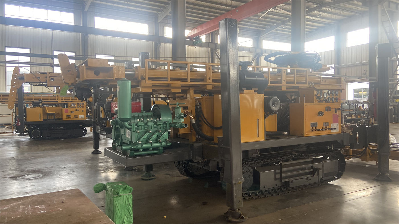
The hole diameter range of 105–1000 mm and this set of torque values are two sides of the same thing. The larger the hole diameter, the greater the load that must be overcome during rotation, and the higher the requirements for air compressor displacement, drill tool specifications, and casing. Therefore, hole diameter is not something that “can be drilled once selected”; it must be checked together with torque, lifting force, and air pressure. The data clearly states that in actual projects a reasonable hole diameter should be selected according to the well completion objective.
Air pressure and air consumption: the cuttings removal link in deep holes is hard to bypass
Regarding drilling methods, the WR1500S data gives three corresponding relationships: top-drive hydraulic rotation for conventional deep water wells and large-diameter drilling; DTH down-the-hole hammer for weathered rock, fractured rock, and intact hard rock; mud rotary for loose formations such as soil, clay, sand, and gravel layers. When using DTH, the recommended working air pressure is 1.65–8 MPa, and air consumption is 16–120 m³/min.
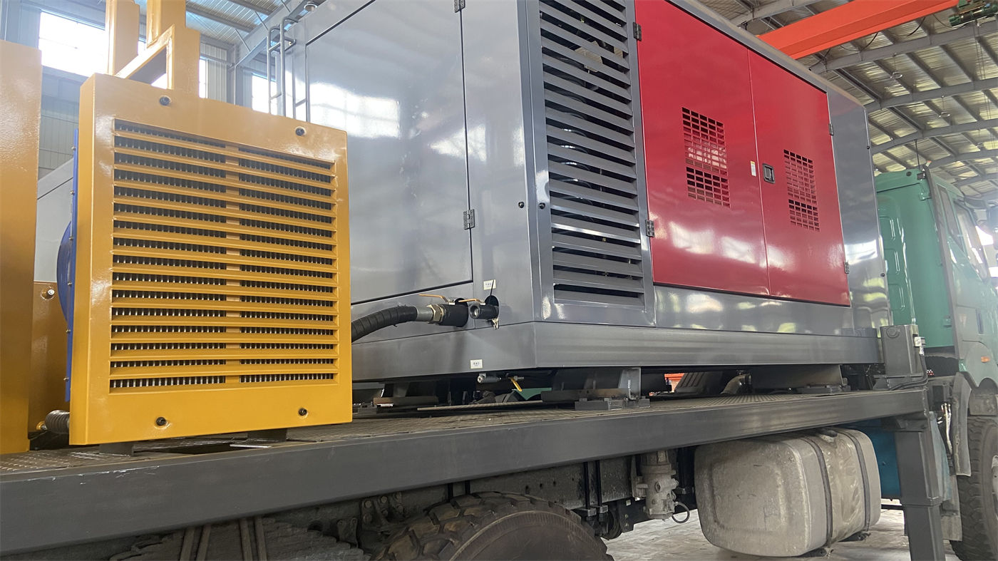
These two values must be read together. In deep-hole and large-diameter hard rock projects, the down-the-hole hammer needs sufficient pressure to drive impact, and cuttings return at the hole bottom needs sufficient displacement to carry rock fragments upward. If either pressure or displacement is lacking, insufficient impact, difficult cuttings removal, or accumulation of cuttings at the hole bottom will occur. In other words, the equipment specification table lists a recommended range, but whether the actual operation can fall within that range depends on the air compressor capability provided on site; this part is not a parameter of the drilling rig itself.
The upper hole section and the deep aquifer are two sets of constraints
The construction conditions mentioned in several data items are worth separating: for soil, clay, sand, and gravel layers, mud rotary, casing, or other wall protection methods may be used, and a stable borehole should be established first during the opening stage; only after entering rock should switching to DTH be considered; after entering the main aquifer, water inflow will change cuttings removal in the hole and the working state of the down-the-hole hammer. The depth of the main water-producing layer should be recorded, and air supply, hole cleaning, and casing methods should be adjusted accordingly.
For a 1500 m class hole, once the upper hole section shrinks or collapses, it will directly affect subsequent deep construction. This type of constraint cannot be bypassed by increasing the drilling depth number. When encountering weathered rock, fractures, or fault fracture zones, the method given in the data is to reduce feed speed, strengthen hole cleaning, and adopt casing, foam, and other hole-stabilizing measures as appropriate. If cuttings return continues to decrease or tripping resistance increases significantly, drilling should be stopped for inspection.
Beyond drilling capability, several other constraints exist at the same time
Putting the equipment into a project adds several types of limitations unrelated to the borehole:
| Constraint | Relevant values in publicly available data | Matters to be arranged in advance |
|---|---|---|
| Transport | Overall machine about 28 T, dimensions about 11.5 × 2.6 × 3.5 m | Flatbed load capacity, road height limits, bridge load capacity, turning space; 9.6 m drill pipes usually need separate transport |
| Site layout | Telescopic mast structure, crawler travel 3.5 km/h, gradeability 21° | Positions of air compressor, mud system, drill tools, and material area; space for internal relocation on the site |
| On-site lifting | 5 T large auxiliary winch, 2.5 T small auxiliary winch | Handling organization, rated loads, and safety distances for down-the-hole hammers, drill pipes, and casing tools |
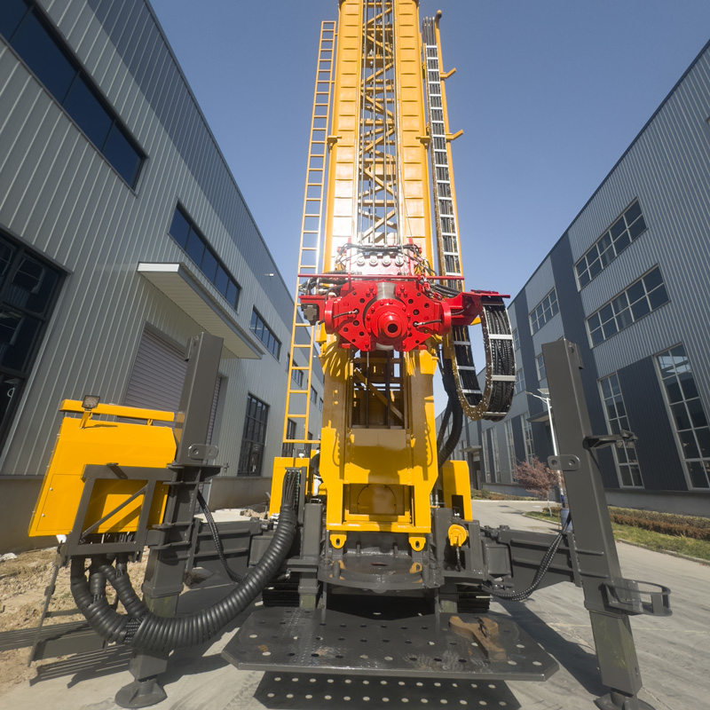
The role of the telescopic mast in this data is clearly stated: while ensuring the working height required for deep-hole construction, it can improve the overall machine envelope in transport condition. For 28 T class equipment, this corresponds to loading and passage conditions, not drilling efficiency. The 9.6 m drill pipe corresponds to the number of connections—long drill pipes reduce connection frequency, but at the same time require sufficient operating space at the construction site and more standardized drill pipe handling organization. Both are organizational conditions and will not be solved automatically by an increase in the drilling depth figure in the specification table.
Parts not covered in the data that need separate confirmation
The publicly available WR1500S data does not give drilling efficiency for specific formations, well completion cycle, casing specification configuration, or wellbore structure under different hydrogeological conditions. The reference drilling efficiency of 10–35 m/h also indicates that actual efficiency, drilling depth, and well completion results should be based on on-site working conditions—because geological conditions, downhole tools, drilling angle, and operating methods vary.
Therefore, at the drilling plan stage, the following items can be checked: how the margin between the target well depth and 1500 m is determined; which segment of 105–1000 mm the target hole diameter falls into; whether the upper overburden uses mud rotary or casing wall protection; which air compressor supplies the DTH air pressure and air consumption for the deep hard rock section; whether handling and placement space for 9.6 m drill pipes has been reserved in the wellsite plan; and whether the transport plan for the 28 T overall machine plus drill pipes has been checked against road conditions. Once these conditions are clear, discussing whether the 1500 m class level is suitable is more practical than looking only at the drilling depth number.