












Discussions of kilometer-deep well projects usually begin with "how deep can it drill." But when hole depth reaches the 1000-meter level, the equipment parameters themselves are only the starting point: whether the same 1000-meter-class rig can complete two different wells on schedule often depends on whether several matters were settled in advance before work began. Using the public information on this site's WR1000S as a reference, this article breaks down item by item the preliminary tasks in such projects that are easily postponed until after the rig enters the site, explains which verified equipment parameters each task corresponds to, and which conditions must be separately confirmed on site.
First Clarify: Which Tasks Are "Preliminary" and Which Can Only Be Decided on Site
Preliminary work is not about completing the entire construction plan, but about fixing in advance those conditions that are very difficult to change once the equipment enters the site. For kilometer-deep water well projects, these matters usually directly affect every subsequent process: how the drill string is configured, how the in-hole process is divided into stages, how the mast and drill pipe length are combined, how the entire machine is transported in, and how the site bears the load. Their common characteristic is that the cost of change rises rapidly with the start of work.
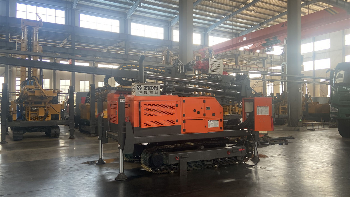
The key values given in the public information on the WR1000S include: maximum drilling depth 1000 m, hole diameter 105–800 mm, lifting force 52 T, dual-condition rotary torque 26000/13000 N·m, corresponding maximum rotation speeds 70/140 r/min, diesel power 194 kW, 6 m drill pipe, recommended drill pipe diameter 114 mm, overall weight approximately 17.8 T, dimensions approximately 7.3×2.25×2.75 m, travel speed approximately 5 km/h, maximum gradeability reference 21°, hydraulic outrigger stroke 1.7 m, and auxiliary winch lifting force 2.5 T. These values constrain different stages respectively and cannot be read together as a single overall capability table.
Item One: Pre-Assess the Drill String and Process by Hole Section, Not by Whole-Well Average
At 1000-meter-class hole depths, the drill string's own weight, borehole wall friction, and casing weight all accumulate with depth. The information gives this equipment a lifting force of 52 T and an axial load of 8 T. The significance of this value is not "how much it can lift," but whether there is margin during normal tripping, deep-hole drill tool recovery, and some large-specification casing operations. If the casing running depth, casing running method, and number of trips have not been estimated before work begins, it is easy to discover insufficient margin only when in-hole resistance rises.
The rotary part also needs staged pre-assessment in advance. The torque set of 26000/13000 N·m corresponds to output under two different resistance states; the lower-speed, high-torque condition is closer to large-diameter, hard rock, and high-friction hole sections, while the higher-speed gear corresponds to stages with relatively lower resistance. It constrains the choice for different hole sections, not the operating habits of a two-speed gearbox. As the same well is drilled from upper overburden into deep aquifers, the resistance state changes; what is pre-assessed is "which section uses which gear," not a single fixed value for the entire well.
Process staging also needs an initial assessment before work begins. According to the information, complete hard rock can be drilled by DTH with medium- and high-pressure down-the-hole hammers, with recommended working air pressure 1.6–8 MPa and air consumption 16–96 m³/min; soil, clay, sand, and gravel layers can use mud rotary drilling. For 1000-meter-class deep holes, the cuttings removal distance is long. If cuttings removal is insufficient, sediment and regrinding are likely to form, further increasing torque and energy consumption. This means the air compressor's pressure and displacement are not selected based on the single figure of "maximum hole depth," but must be comprehensively determined in combination with the DTH hammer model, hole diameter, hole depth, altitude, and rock hardness. This item usually needs to be checked with the supporting party before the equipment enters the site, because insufficient displacement directly affects impact and cuttings removal efficiency.
Item Two: Decide the Mast Type and Drill Pipe Length Combination First
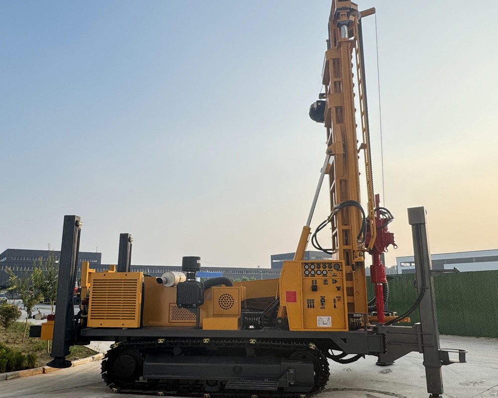
The S in the WR1000S model represents a telescopic mast. For a 1000-meter-class heavy-duty drilling rig, transport and on-site relocation are themselves part of project organization: the telescopic mast can reduce the overall machine's outer dimensions in transport state while maintaining the working height required for deep-hole construction in operating state. The applicable condition for this feature is that the project needs to move between multiple hole locations or sites, and the transport roads have certain restrictions on outer dimensions. If the project is fixed at one location for long-term construction and road conditions are ample, the value brought by the telescopic mast will correspondingly weaken. This point is not expanded in the information and is a part that needs to be judged according to project conditions.
The choice of drill pipe length directly changes the number of connections and auxiliary time. The information states that the WR1000S supports 6 m drill pipe, with recommended drill pipe diameter 114 mm. If too-short drill pipe is used for 1000-meter-class drilling, the number of connections will increase substantially, and auxiliary time and labor intensity will also accumulate rapidly. Therefore, determining "how long the drill pipe is, how many rods to prepare, and how to place and handle them on site" before work begins is more controllable than making temporary adjustments based on progress after entering the site. Drill pipe threads, straightness, and fatigue condition are items that need to be included in continuous inspection. The information does not give a specific replacement cycle or inspection frequency; this part should be separately confirmed according to the manufacturer's instructions and actual on-site conditions.
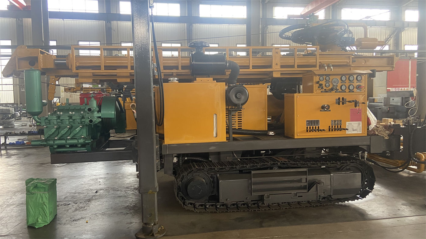
Supporting the drill pipe are also on-site lifting and auxiliary handling capabilities. The WR1000S's auxiliary winch lifting force is 2.5 T, which can be used for handling DTH hammers, drill pipes, casing tools, and on-site accessories. Ultra-deep hole projects have more and heavier supporting drilling tools, so lifting routes and material placement areas need to be planned before work begins to avoid occupying the main machine's operating space. This item will not appear in the parameter table, yet it is often the main variable in on-site order.
Item Three: Overall Machine Transport and Site Bearing Conditions Must Be Settled Before the Equipment Enters the Site
An overall weight of approximately 17.8 T and dimensions of approximately 7.3×2.25×2.75 m are the first two conditions tested when this equipment enters the site. During transport, it is necessary to confirm flatbed load capacity, road width limits, height limits, and bridge bearing capacity; the telescopic mast must be reliably locked, and 6 m drill pipes and casing should be secured separately. These are transport preparation matters, already clearly noted in the information, and operational details are not expanded here.
On site, the hydraulic outrigger stroke of 1.7 m can help level and stabilize the equipment on uneven platforms. Kilometer-class construction cycles are long, and the equipment's level state affects mast stress, hole deviation, and operating condition, so soft ground should use pads of sufficient area to prevent long-term settlement. Travel speed is approximately 5 km/h, and maximum gradeability reference is 21°—these two values are mainly used for relocation within the site and between hole locations. Before actual movement, road bearing capacity, slope, turning radius, and soft ground conditions should be confirmed. The information does not give ground contact pressure values or bearing requirements for this equipment on specific soil types, so whether the site meets bearing conditions needs to be separately confirmed after on-site survey.
The determination of equipment positioning will in turn affect subsequent processes. For example, the distances between the hole location and the material storage area, lifting route, cuttings removal channel, water source or mud circulation pit all affect the auxiliary time of one trip. These contents fall within the scope of construction organization and cannot be covered by equipment parameters, but in kilometer-class projects, once the hole location is set incorrectly, the cost of change increases with hole depth.
Several Matters Easily Left Until After Entering the Site
Looking at the above items together, one common point emerges: none of them belong to the in-hole drilling action itself, yet all directly affect whether drilling can proceed continuously. For kilometer-deep well projects, a single trip takes a long time. Once a preliminary condition is not settled, the cost of stopping to deal with it will be significantly higher than for small- and medium-depth projects.
- Whether the drill string configuration and casing plan form a margin relationship with the 52 T lifting force and 8 T axial load;
- Whether the two rotary torque gears are divided in advance by hole section, rather than switched by feel after work begins;
- Whether the air compressor pressure and displacement are calculated according to the DTH hammer, hole diameter, hole depth, altitude, and rock hardness;
- Whether the quantity, placement, and lifting route of 6 m drill pipes match the 2.5 T auxiliary winch capacity;
- Whether the overall machine transport plan, site bearing capacity, and outrigger pads are settled before entering the site.
Which Conditions Are Not in the Information and Need Separate Confirmation
The public information on the WR1000S covers the main capability values and some applicable working conditions, but the following types of information are not given in the information and fall within the scope that should be separately confirmed with the manufacturer or relevant parties before work begins:
- Ground contact pressure and gradeability safety boundaries under specific soil or formation conditions;
- Recommended replacement cycles and inspection standards for drill pipes, drilling tools, and casing;
- Power system derating under different altitude and temperature conditions;
- The matching relationship between the mud circulation system, water pump, and this equipment;
- Specific locking requirements and inspection items for the telescopic mast in transport state;
- Passage conditions related to local road height limits, width limits, and bridge bearing capacity.
By aligning preliminary work with equipment information, it can be seen that this 1000-meter-class drilling rig provides a set of capability upper limits and operating conditions, not a complete construction organization plan. To turn these values into executable arrangements in a specific project, each item still needs to be implemented on the basis of on-site survey, hydrogeological data, and the supporting equipment list. Parts not covered by the information should not be replaced with values from other models, nor should they be inferred by generalizing under the "1000-meter-class" category.