












Slope anchor holes, foundation pre-drilling, and quarry bench holes are all called "drilling" by water well construction crews, but their equipment capability requirements are not on the same line as water well drilling. The operational objective of shallow holes in hard rock engineering is usually to drill a hole within a few dozen meters through the rock formation according to the designed hole position, direction, and diameter, and then withdraw, while the objective of water well drilling is to drill the well to the aquifer, complete the well, and ensure water yield. Different objectives mean different capability items that the equipment must prioritize. Using the publicly available information on this site's DTH30C as a reference, this article explains where the directional differences between the two types of operations fall in specific terms.
First, clarify the success criteria for each type of operation
The success criteria for water well drilling can be broken down into four things: drilling to the predetermined aquifer depth, achieving the well diameter required for designed well completion, maintaining a stable well wall for casing installation, and meeting the water supply target with water yield. Around these four things, the capability items of a water well drill usually start with maximum drilling depth, lifting force, rotary torque, and the matching capability of the mud pump or air compressor.
The success criteria for shallow holes in hard rock engineering are not about reaching a certain depth, but about drilling the hole to the designed parameters, penetrating the rock formation, keeping deviations in hole position and direction controllable, and enabling the equipment to continuously move between holes. Taking DTH30C as an example, the information lists a maximum drilling depth of 30 m, a drilling diameter of 76–280 mm, a maximum rotary torque of 3500 N·m, and a suitable rock hardness of approximately f = 8–24. This set of values indicates the positioning of an engineering equipment unit for shallow-to-medium holes and medium-to-high hardness rock formations. Its capability lies not in drilling deeper, but in making shallow holes in hard rock according to design.
In hole depth and hole diameter, the two types of equipment have different orientations
The capability items of water well drills unfold mainly around drilling depth. For a 300-meter-class or 500-meter-class unit, the key value is maximum drilling depth, and the matching lifting force, drill pipe length, and mast height are all configured around delivering the drill string to that depth. The hole diameter range is usually also relatively wide, but wide diameters mostly appear in the upper hole section, while the deep section often narrows.
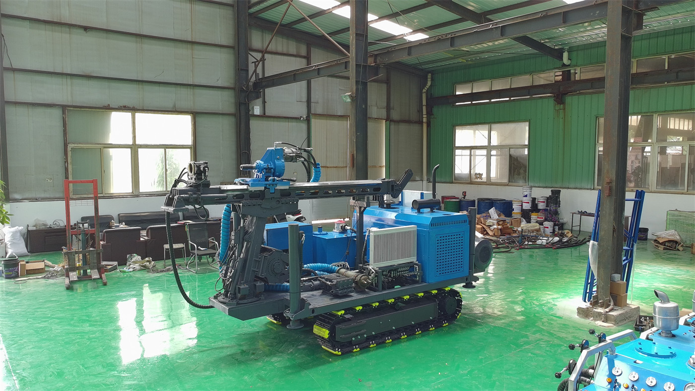
The DTH30C is positioned at the 30 m level, and its hole diameter of 76–280 mm remains roughly usable throughout the entire hole depth range. The difference in this orientation is that its capability is not measured by "how deep it can go," but by "how large a shallow hole it can drill in how hard a rock formation." For operations such as slope anchor holes, anchor cable holes, and foundation pre-drilled holes, where the hole depth is usually within twenty to thirty meters but the hole must pass through hard rock, a 30 m drilling depth is sufficient; for water wells of 200 m, 300 m, or more, this drilling depth figure itself is already beyond the boundary.
Rotary torque constrains effective drilling in hard rock sections
In hard rock drilling, rotary torque must overcome the cutting resistance of the drill bit in the rock and the additional load of the down-the-hole hammer. The maximum rotary torque of 3500 N·m given for the DTH30C corresponds to the drilling requirements of medium-to-high hardness rock formations within the 76–280 mm hole diameter range. In engineering projects, hole positions are scattered and rock hardness varies greatly; insufficient torque manifests as continuously increasing rotary resistance, drill bit bouncing, and stagnation of penetration at the hole bottom.
The torque configuration logic of water well drills is different. Within the well depth range of 200–500 m, rotation must simultaneously overcome the self-weight friction of the drill string, the resistance of the hole wall, and the rock cutting resistance. The torque value is more often back-calculated from depth and well diameter, rather than based on the hardness of a single rock formation. When the torque values of the two appear close, they are not governing the same thing.
The cuttings removal method determines different supporting conditions
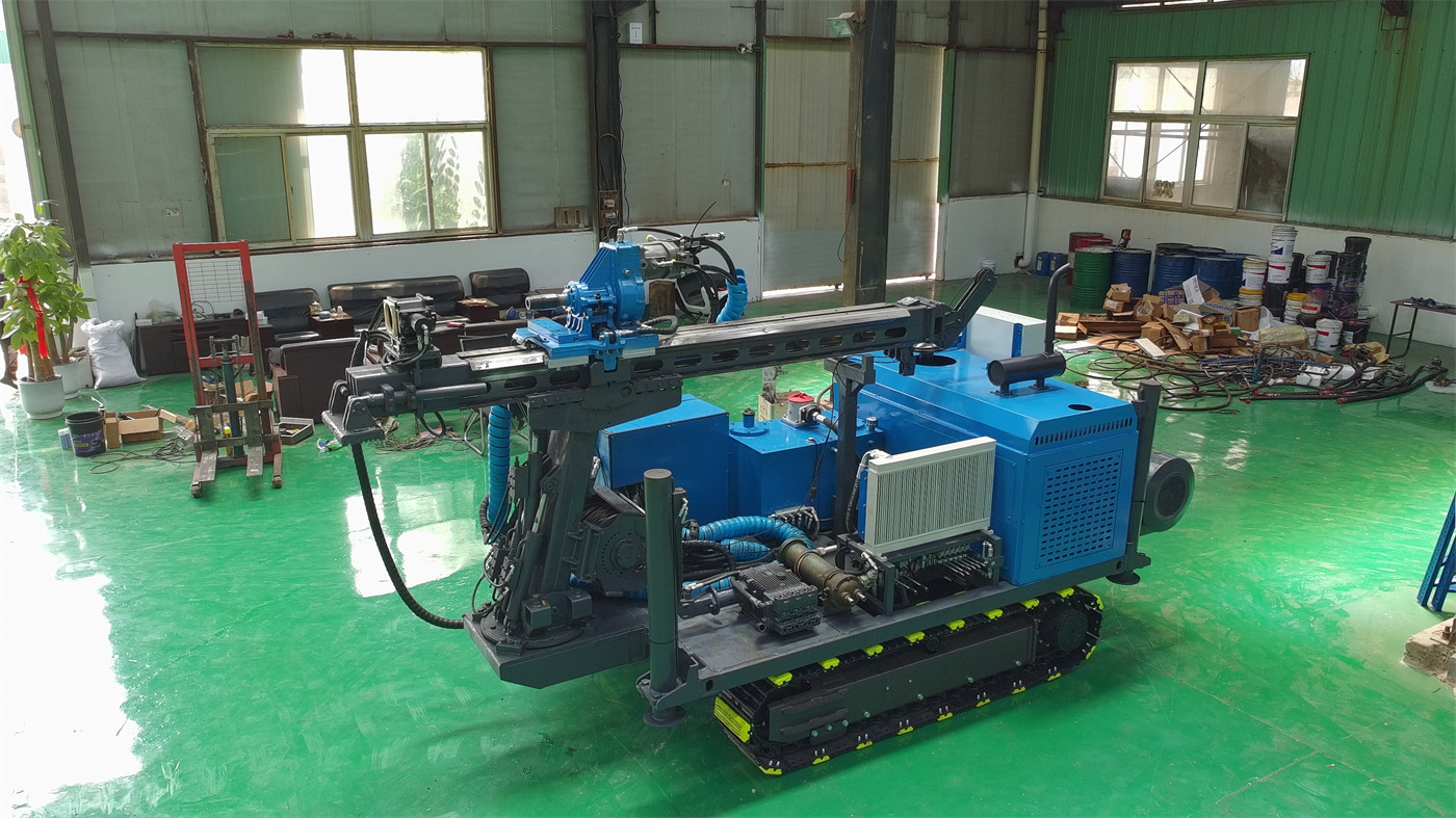
The DTH30C uses down-the-hole drilling, in which compressed air simultaneously drives the down-the-hole hammer and discharges rock cuttings. The reference air consumption in the information is approximately 8 m³/min (the original information is marked as 8 m²/min; this article interprets it as m³/min according to the commonly used unit for compressed air flow, and the final value should be confirmed in official technical documentation). The core supporting equipment for down-the-hole drilling is the air compressor and the down-the-hole hammer, not a mud system.
Conventional water well drills mostly use direct or reverse mud circulation in overburden and aquifers. Well wall stability, cuttings return, and downhole pressure all depend on the mud system, with matching mud pumps, mud tanks, and solids control equipment. The two types of equipment need to carry different materials, and their site organization is also different. A water well drill can switch to a DTH down-the-hole hammer when it reaches a hard rock section, but the baseline of the entire process is still mud circulation; an engineering down-the-hole drill such as the DTH30C is organized around compressed air from the moment it enters the site, with no supporting position for a mud system.
Operation organization is oriented toward different events
The rhythm of water well drilling revolves around completing all processes for one well: opening the hole, running casing, changing layers, completing drilling, installing the pump, and test pumping. The time a unit stays at one well site is measured in days.
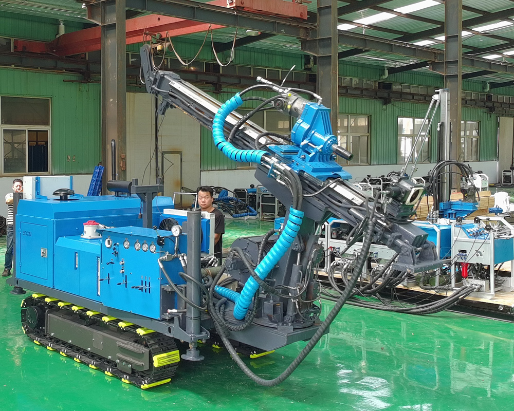
The operation organization of the DTH30C is oriented toward scenes with dense and constantly changing hole positions. The information lists a swing angle of 18–180°, tilt adjustment capability, a carriage stroke of 3.2 m, an effective stroke of 2.2 m, a crawler chassis, overall dimensions of approximately 3200 × 1200 × 1850 mm, and an overall weight of approximately 2500 kg. These configurations together point to rapid hole-by-hole operation rather than long stays at a single well. The 18–180° swing angle corresponds to the multi-angle posture requirements of slope anchor holes and anchor cable holes, rubber tracks for protecting hardened ground correspond to urban and plant construction, and the compact shape corresponds to narrow sites.
Putting them in one table
| Capability item | Orientation for shallow holes in hard rock engineering | Orientation for conventional water well drilling |
|---|---|---|
| Hole depth positioning | Within a few dozen meters, designed by hole type | Mainly based on target aquifer depth |
| Hole diameter range | Roughly usable throughout the entire hole depth | Wide at the top, narrowing at depth, adjusted with completed well casing diameter |
| Cuttings removal method | Compressed air drives the down-the-hole hammer and removes cuttings | Mainly direct and reverse mud circulation; can switch to DTH in hard rock sections |
| Operation organization | Dense hole positions, frequent hole changes | Long stay at a single well, processes revolve around well completion |
| Main supporting equipment | Air compressor, down-the-hole hammer, drill bit, casing tools | Mud pump, mud tank, drill pipe, well completion casing |
Where boundaries are easily crossed when mixing the two types of equipment
- Using a 30 m-class engineering down-the-hole drill as deep water well equipment—the DTH30C in the information has a maximum drilling depth of 30 m and is not suitable for water wells of 200 m, 300 m, or more.
- Viewing the multi-angle swing and crawler mobility of a down-the-hole drill as enabling it to replace a water well drill at any hole position—its strengths lie in engineering hole posture and hole-changing rhythm, not in well completion processes.
- Directly transferring the drilling depth figure of a water well drill to an engineering hole scenario—drilling depth is only one capability limit of water well equipment; hole diameter, hole direction, posture control, and hole-changing speed are equally important for engineering holes.
- Understanding the "53 m/min feed speed" of down-the-hole drilling as the rock penetration rate—the information clearly states that this is the rapid movement speed of the feed mechanism, mainly used for power head return, drill pipe handling, and non-drilling actions. Actual penetration is jointly affected by rock hardness, hole diameter, down-the-hole hammer specifications, air compressor capability, and drill bit wear.
If the operation objective leans toward engineering shallow-to-medium holes, matters to confirm in advance
After the direction is determined, selection still requires verifying several conditions not fully covered by the machine information:
- Whether the rock hardness falls within the range of f = 8–24; when hardness and abrasiveness are higher, the specifications of the down-the-hole hammer and drill bit need to be recalculated.
- Whether the compressed air supply can stably reach the reference value of approximately 8 m³/min in the information, and the air consumption unit should ultimately be based on official technical documentation.
- The tilt adjustment function does not give a specific angle range; actual project design should be based on the final production configuration and technical confirmation documents.
- Whether the turning space of the access route, ground bearing capacity, underground pipelines, and surrounding buildings match the overall dimensions of 3200 × 1200 × 1850 mm and the overall weight of approximately 2500 kg.
- Whether a dust collector or water mist dust suppression system is required, as well as local construction regulations for dust and noise.
If the operation objective leans toward water well drilling, the drilling depth and process route of the DTH30C are outside its applicable scope, and judgment should return to the drilling depth, lifting force, torque, pump volume, and well completion conditions of water well drills. The two types of equipment can each have their own division of labor, but using one type as the other will directly encounter capability boundaries in hole depth, well completion, or supporting processes.