












Looking through the CR800P data, the drilling depth row lists BQ 920 m, NQ 800 m and HQ 380 m; the feed system column lists a thrust force of 67 kN and a hoisting force of 130 kN; the mud unit lists a flow rate of 100 L/min and a pressure of 7 MPa. These three groups of figures sit in three different columns, not close together on the page, so it is easy to read each on its own. But together they answer the same question: at a given hole depth and hole diameter, can this rig pull the drill string out smoothly and continuously carry cuttings out of the collar? This article follows that question in order, explaining which part of the operation each group of figures governs and why they must be read together.
The three groups of figures represent three different kinds of quantity in the parameter table
Drilling depth is not the output value of any one component; it is the reference drilling depth this rig offers under specific drill-string specifications and techniques. The CR800P lists three depths for the BQ, NQ and HQ specifications, which shows that this number is tied to the drill pipe, bit and core-barrel system, and changes when the specification changes. Hoisting force and thrust force are force values of the feed system, in kN, constraining the ability of the power head to move the drill string up and down. Mud pressure and flow rate belong to the circulation system, constraining whether flushing fluid can be delivered to the hole bottom and carry cuttings back to the surface. The three have different units and belong to different systems; they cannot be converted into one another, nor can one be inferred from another.
The drilling depth figures must be read together with the drill-string specification
The three reference drilling depths of the CR800P are BQ 920 m, NQ 800 m and HQ 380 m. If an exploration line switches from NQ to HQ, the reference depth drops from 800 m to 380 m. This is not because the rig has become weaker, but because with a larger hole diameter the drill-pipe cross-section, annulus volume, drill-string weight and cuttings volume all change. When reading the drilling depth row, first confirm which specification the project plans to use for coring, then compare against the figure in the corresponding cell. Treating the NQ figure of 800 m as "this machine can drill 800 m at any hole diameter" is the most common out-of-bounds reading.
Drilling depth is also only a reference value. The data itself does not state under what rock type, hole angle or hole structure these depths are given. Multi-angle drilling from 45° to 90° is a feature of this rig, but inclined holes and vertical holes differ in drill-string friction and in the conditions for cuttings to return upward; whether the same drilling depth figure holds at a specific inclination must be judged separately according to site conditions.
Hoisting force constrains the drill-string handling margin in deep-hole sections
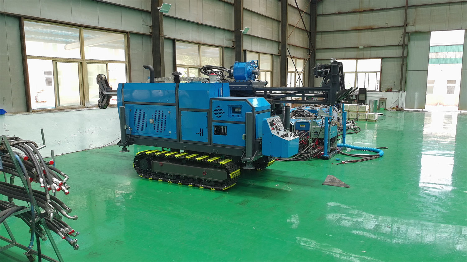
The CR800P has a hoisting force of 130 kN and a thrust force of 67 kN. As hole depth increases, the self-weight of the drill string and the friction against the hole wall accumulate, and the resistance to be overcome when pulling out also increases. This is where the relationship between hoisting force and drilling depth lies: it determines how much margin the feed system still has, near the reference depth, to handle normal drill-string weight and downhole resistance.
Another bundled value is the maximum clamping force of the clamp, 130 kN, the same as the hoisting force; the clamp through-hole capacity is 54–127 mm, and the maximum applicable drill-pipe diameter is 114 mm. These figures should be read together: whether the hoisting force can be used depends on whether the clamp can grip the drill string of the corresponding specification and whether the drill-pipe diameter falls within the through-hole range. The data does not further break down the 130 kN value into allowable values at different hole depths and inclinations, so it cannot be directly understood as "capable of providing 130 kN of net hoisting capacity in any 800 m hole".
The CR800P wireline winch has a rope capacity of 1000 m (6 mm wire rope), a hoisting speed of 116 m/min, an empty-drum hoisting force of 11.5 kN and a full-drum hoisting force of 5.6 kN. This group of figures corresponds to the hoisting step for the wireline core barrel and is a separate mechanism from the feed system's hoisting force; the two cannot substitute for each other. When wireline coring at the 800 m level, the margin left by the 1000 m rope capacity is the operating space on the core-barrel hoisting side.
Pump pressure corresponds to whether circulation can be maintained, not to how fast drilling goes
The mud unit's parameters are a plunger high-pressure pump, hydraulically driven, with a flow rate of 100 L/min and a pressure of 7 MPa. As hole depth increases, both the downward path of the flushing fluid along the drill pipe and the upward return path along the annulus lengthen, and the friction losses rise; in hole sections with developed fractures, unstable returns or losses, the pressure conditions needed to maintain circulation change again. The 7 MPa figure shows that this pump station has a certain pressure output capability and can serve as a starting point for discussing complex circulation conditions.
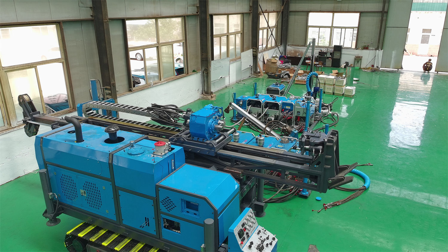
But it cannot by itself lead to the conclusion that "circulation can definitely be established at this hole depth". Whether the mud pressure is sufficient also depends on hole diameter, annulus cross-sectional area, drill-pipe specification, flushing-fluid properties and the degree of formation loss, none of which are given item by item in the data. The flow rate of 100 L/min and the pressure of 7 MPa are also two independent parameters; when pressure is sufficient but flow is insufficient, the upward return velocity of cuttings may likewise be inadequate, so the two must be judged under the same circulation condition.
Putting the three rows of figures back under the same hole-depth condition
The table below only summarizes the relevant figures from the CR800P data, to show which part of the operation each item corresponds to as hole depth increases; it does not imply any conversion relationship among the three.
| Parameter item | Data value | Which part of the operation it corresponds to as hole depth increases |
|---|---|---|
| Reference drilling depth | BQ 920 m / NQ 800 m / HQ 380 m | Defines the drill-string specification under which hole depth is discussed |
| Thrust force / hoisting force | 67 kN / 130 kN | Force margin when running in and pulling out the drill string |
| Wireline winch rope capacity | 1000 m (6 mm wire rope) | Operating space for hoisting the wireline core barrel |
| Mud flow rate / pressure | 100 L/min / 7 MPa | Circulation conditions for flushing-fluid delivery and cuttings return |
The order of associated reading can go like this: first lock in the corresponding reference drilling depth according to the coring specification, to define the scope of discussion; then look at the drill-string self-weight and expected downhole resistance at this hole depth, compare against the hoisting force and clamp capability, and judge whether there is margin in the tripping step; finally look at the circulation side, comparing the pump's flow rate and pressure against hole diameter, drill pipe and formation loss to judge whether cuttings can be continuously returned. If any one of the three conditions is insufficient, no matter how ample the other two figures are, the hole cannot be completed smoothly.
It should be noted that this kind of associated reading can only indicate direction, not calculate a conclusion. The data does not provide drill-string weight tables at different hole depths, annulus return velocity requirements at different hole diameters, or correction values for hoisting force as inclination changes. All of these need to be calculated separately according to the specific drilling design and site conditions.
Supporting conditions are also on this relationship chain
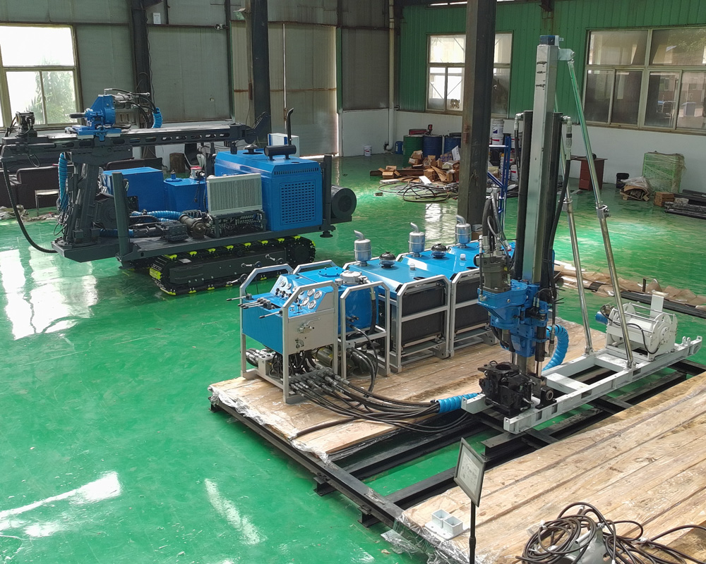
On the power system side, the CR800P requires a diesel engine power of ≥99 kW, and a 22 kW × 3 electric motor configuration can also be used. During continuous rotation and circulation in deep-hole sections, whether the power output is stable indirectly affects pump pressure and torque performance; fuel transport, power generation conditions and maintenance resources in remote mountainous areas are site conditions to be verified when choosing between diesel and electric options. The split structure allows the power, control, mud and drilling units to be transported separately, improving access to mountainous hole locations, but the state of the hydraulic quick-change couplings and connectors after each module is assembled must be checked after every assembly, a point listed separately in the data.
Parts beyond the data that need confirmation with the manufacturer and on site
- The rock type, hole angle and hole structure conditions corresponding to the reference drilling depths of NQ 800 m and HQ 380 m are not explained item by item in the data.
- There is a lack of breakdown data by hole depth and inclination for the actual available margin of the 130 kN hoisting force near the reference depth.
- Whether the 7 MPa pump pressure is sufficient to maintain circulation in fractured or loss-prone hole sections needs to be judged together with hole diameter and formation.
- For the matching relationship between the power head's maximum torque of 980 N·m and maximum speed of 1200 rpm and different rock types, the data gives only switching principles, not a parameter combination table.
- The combination of the feed stroke of 1.8 m with applicable drill-pipe lengths of 1 m / 1.5 m affects the frequency of rod connections and auxiliary time; the specific organization method must be determined according to the site layout.
Therefore, when reading these three rows of figures for the CR800P, rather than comparing which number is larger, first determine which coring specification the project uses, how deep it plans to drill, and what the expected downhole resistance and loss conditions are, then compare item by item against the corresponding figures in the data, and list the conditions not covered as matters to be confirmed before mobilization. The data can provide the direction of the capability boundary; the final drilling depth and efficiency are still subject to site working conditions.