












In water well drilling rig selection, a common misunderstanding arises: if a project has a 600 m class deep well requirement, people look directly at a model rated at 600 m; conversely, once a 600 m class rig is purchased, they assume every well can be drilled to 600 m. Neither assumption holds up to scrutiny. The maximum drilling depth of 600 m in the WR600S information on this site describes the upper limit of the equipment's capability, not a construction plan. Whether this depth can be approached in an actual project also depends on hole diameter, formation conditions, aquifer position, drill string management, and well completion structure.
Maximum drilling depth describes the upper limit of equipment capability
In the WR600S information, the maximum drilling depth of 600 m appears alongside a hole diameter range of 105–400 mm. These two ranges are not independent parameters: as hole diameter increases, the volume of cuttings to be returned, drilling tool friction, and required air or pump volume all rise, and the conditions under which the 600 m upper limit holds become tighter. Therefore, 600 m is better understood as the upper limit of the hole depth range the rig is expected to cover, not a default final construction depth.
The hydrological design of a water conservancy or water supply project is usually determined by aquifer burial depth, required water yield, and the casing and pump plan. Equipment parameters only confirm whether that depth can be covered; they cannot reverse the requirement so that "because the rig is 600 m class, every well must be drilled to 600 m."
Hole diameter and drilling depth are constraints that must hold simultaneously
The 105–400 mm given in the information is a wide hole diameter range, but the two endpoints of that range do not support the 600 m upper limit to the same degree, and this also depends on formation. Advancing a deep hole in the small-diameter range through relatively intact hard rock is completely different from advancing a deep hole in the large-diameter range through thick upper overburden or fractured broken zones, in terms of rotary load, cuttings return pressure, and hole wall problems.
- Small diameter, intact hard rock section: more suitable for continuous advancement with a down-the-hole hammer, with a relatively generous proportion of cuttings return channel area.
- Large diameter, overburden or broken zone: hole wall stability and cuttings volume are more prominent, and wall protection and hole cleaning plans must be considered first.
- Depth superimposed on diameter amplifies: with each additional section drilled, drill string weight, thread load, and hole wall friction accumulate.
Therefore, the same 600 m figure corresponds to very different construction organization methods under small-diameter and hard rock conditions versus large-diameter and loose overburden conditions.
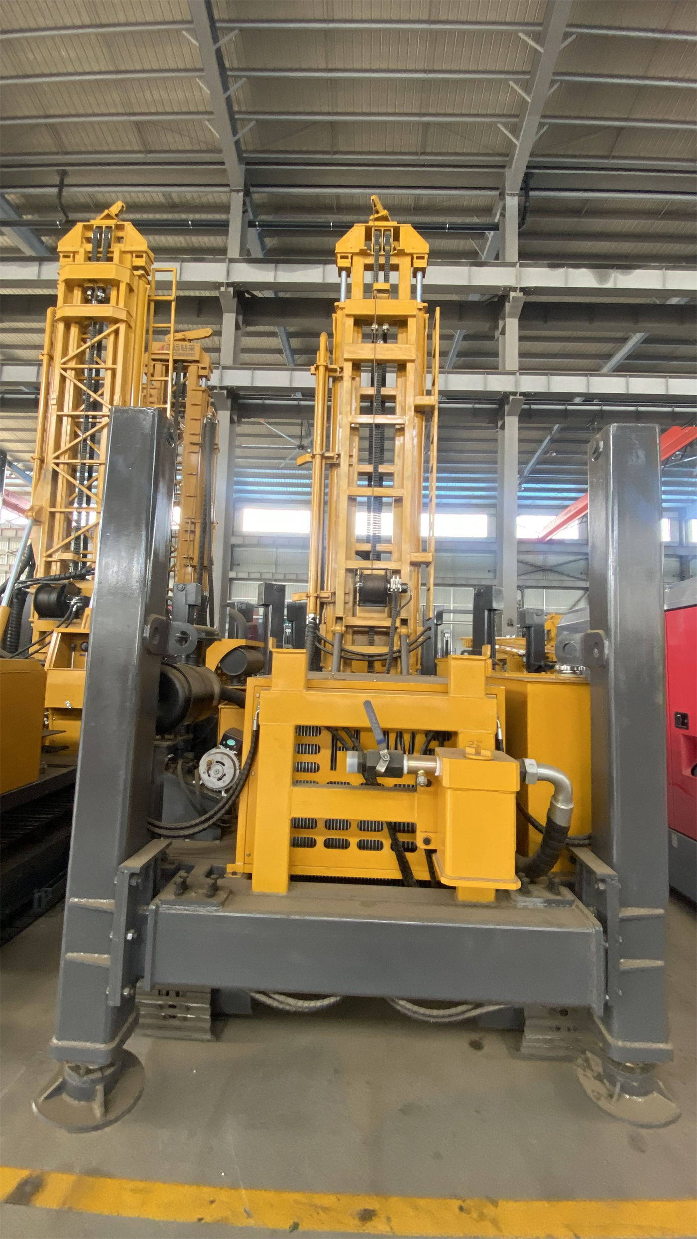
Formation structure determines the actual final hole depth
The information classifies the formations to which the WR600S applies: relatively intact hard rock can be paired with medium- and high-pressure down-the-hole hammers; weathered rock and alternating soft-hard formations tend to show fast penetration but hole wall sloughing and diameter reduction; soil, clay, sand, and gravel overburden support mud rotary drilling; fractures, broken zones, and air-loss formations are prone to sloughing, diameter reduction, air loss, and even sticking.
These classifications mean that whether a well can be advanced to a depth close to the equipment's upper limit depends largely on whether the upper hole section can remain stable, whether the middle section has severe air loss, and at what depth the main aquifer appears. If casing can be used in the upper weathered layer to stabilize the hole section, hole wall problems in the later deep section will be correspondingly reduced; if obvious air loss is encountered in a broken zone, the fracture and cavity conditions should be assessed rather than simply increasing air compressor pressure.
Lifting capacity and drill string management are directly tied to hole depth
In the WR600S information, the lifting capacity is 35 T, the axial pressure is 6 T, and the recommended drill pipe diameter is 89/102 mm with a drill pipe length of 6 m. The pull-out load in deep hole operations is not just the drill pipe's own weight; it also includes hole wall friction, casing weight, and additional resistance caused by local diameter reduction. The deeper the hole, the more obvious the accumulation of these loads, and this is precisely the significance of the margin provided by 35 T.
The information also mentions that if pull-out resistance suddenly becomes abnormal, the hole should first be cleaned and the hole wall condition assessed, rather than directly relying on maximum lifting capacity to force a solution. This cannot be read as an operating tip; it can only be read as a constraint: lifting capacity is the upper limit of equipment capability, not a normal load that every deep hole can smoothly reach.
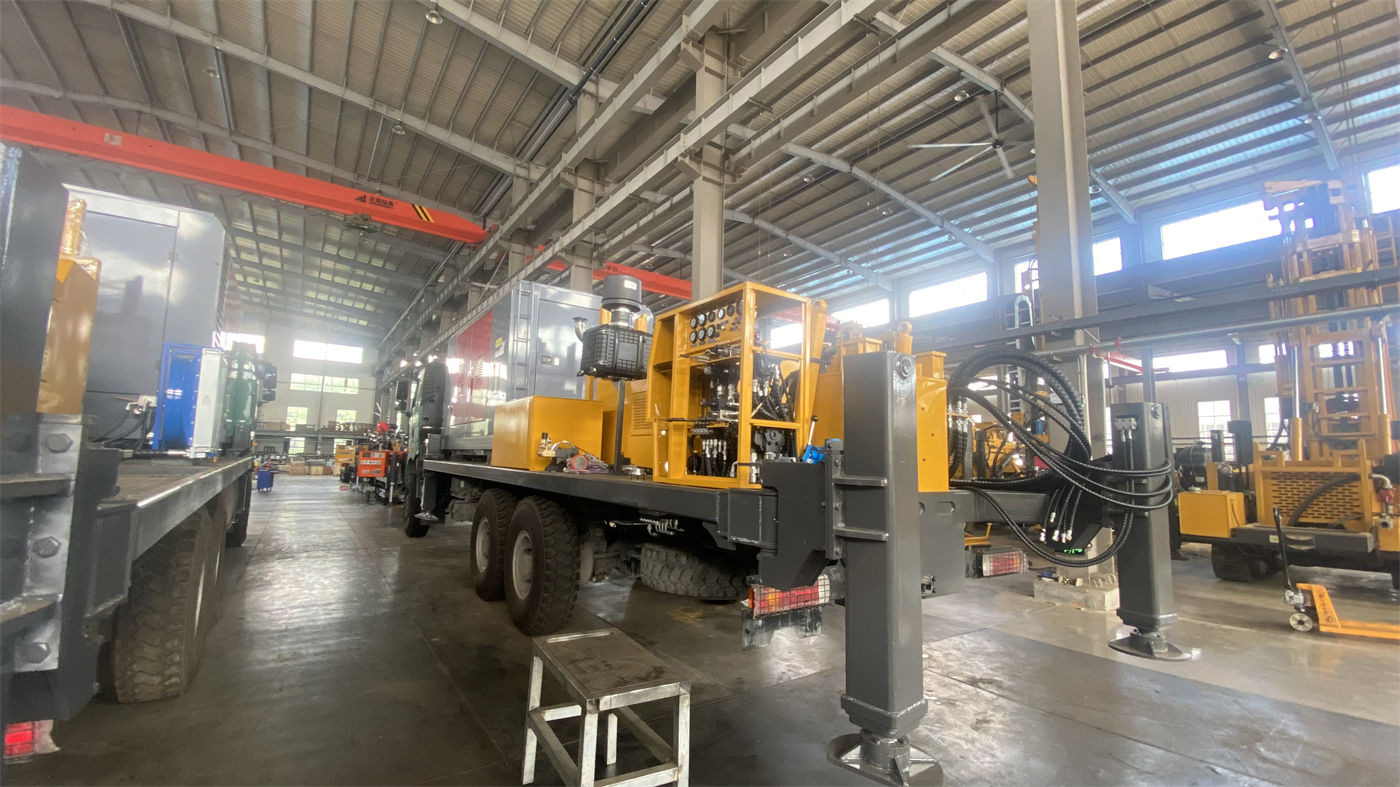
Hole diameter design is determined by water yield and well structure
During well completion, the hole diameter and well structure should be determined according to irrigation area, planned water yield, casing size, and pump type; for long-term pumping projects, the casing, screen, and pump type should also be reasonably designed according to the aquifer and water yield. These points are all stated in the information on this site and point to the same thing: final hole depth and final hole diameter are the result of well completion design, not a simple application of equipment parameters.
Therefore, when a project uses a 600 m class rig, a more reasonable approach is to first determine the aquifer position, planned water yield, and well structure, then use equipment parameters to check whether they can cover it, rather than first assuming 600 m is the target depth and then adjusting other parameters to fit.
Judgments the information can support and matters that need confirmation
| Project information | Judgments supported by the information | Still needs confirmation with the manufacturer or designer |
|---|---|---|
| Final hole depth | Equipment maximum drilling depth of 600 m as the upper limit of coverage | Actual aquifer burial depth and final hole depth design |
| Completed hole diameter | Hole diameter range supported by the information is 105–400 mm | Drilling tool assembly and cuttings return setup for the specific well diameter |
| Formation sections | Hard rock, weathered rock, overburden, broken zone, and aquifer each have corresponding treatment directions | Actual project formation column and hole wall stability plan |
| Pull-out load | Lifting capacity 35 T, axial pressure 6 T | Drill string load estimate under actual hole depth and diameter |
| Process switching | Both mud rotary and DTH down-the-hole hammer have corresponding applicable ranges | Switching depth and matching air compressor displacement and air pressure |
What this table aims to show is that the term "600 m class" only holds at the level of equipment capability. To judge whether a particular well should and can be drilled to near 600 m requires hydrogeological data and well completion design, not a one-time comparison of equipment parameters.
What to ask during selection is not "can it reach 600 m"
Two questions are closer to reality: first, whether the planned final hole depth falls within the equipment's coverage range, and what hole diameter is planned at that depth; second, whether the formation sections and aquifer position at that depth require specific wall protection, casing, or process switching arrangements. The WR600S's 600 m, 105–400 mm, 35 T lifting capacity, 12000/6000 N·m dual-condition torque, 1.2–3.5 MPa working air pressure, and 16–55 m³/min air consumption are all mutually limiting parameters on the same machine and should not be split into single-point comparisons.
If a project only needs a 300–400 m medium-deep well, using a 600 m class rig is not necessarily a wrong choice, but it also does not mean every well must be constructed as a 600 m well. Viewing maximum drilling depth and actual final hole depth separately is the prerequisite for correctly reading selection information.