












Once shallow anomalies are confirmed, the next step is often simplified to "drilling deeper." However, the operational objective of anomaly verification is not to push the hole bottom deeper, but to obtain geological information at greater depths that can be used to judge changes in lithology, alteration, and mineralization. Hole depth is only one path to achieving this objective; if samples cannot be returned, depth records do not match, or the drilling angle deviates from the target body, the verification objective may not be achieved even if the final hole depth exceeds the design value. This article breaks down equipment conditions according to the actual sampling objectives of anomaly verification, and then uses publicly available information on the RC600 to explain which parameters correspond to which needs and which aspects are not covered by the available information.
What anomaly verification actually needs to obtain
Deep anomaly verification in mineral exploration typically needs to answer several questions: whether shallow mineralization or anomalies continue downward, how structural zones and lithology change at depth, and whether mineralization shows zoning or offset. These questions depend on geological information continuously recorded along the hole depth, not on the final hole depth alone. The RC method obtains cutting samples, collected at fixed advance intervals, with on-site geologists recording lithology, alteration, and mineralization before sending samples to the laboratory for assay. Therefore, the first requirement for equipment is not "how deep it can drill," but whether sample return is continuous during drilling and whether the correspondence between samples and depth is clear.
The constraints brought by this objective are distributed across several aspects: the borehole must cover the vertical or inclined extent of the target body; the hole diameter must satisfy the sampling process and drilling tool coordination; the sample return channel must remain stable; the drill string handling capacity must keep up with the weight and friction resistance as hole depth increases; and the drilling angle must be able to pass through the attitude of the target body. The following sections compare these one by one against the relevant parameters in the RC600 information.
Drilling depth and hole diameter: coverage range must be considered together with the sampling method
The RC600 has a maximum drilling depth of 600 m and a hole diameter of 105–450 mm. On its own, 600 m is a depth limit, but the actually achievable depth is affected by hole diameter, drill rods, air compressor, rock formation, hole deviation, and drilling tool wear; the information also describes 600 m as a reference capability under typical configurations. Therefore, to judge whether a piece of equipment is suitable for a particular anomaly verification project, one should first clarify the target depth, collar and final hole diameters, and whether casing is required, then check whether these conditions fall within the equipment's capability range.
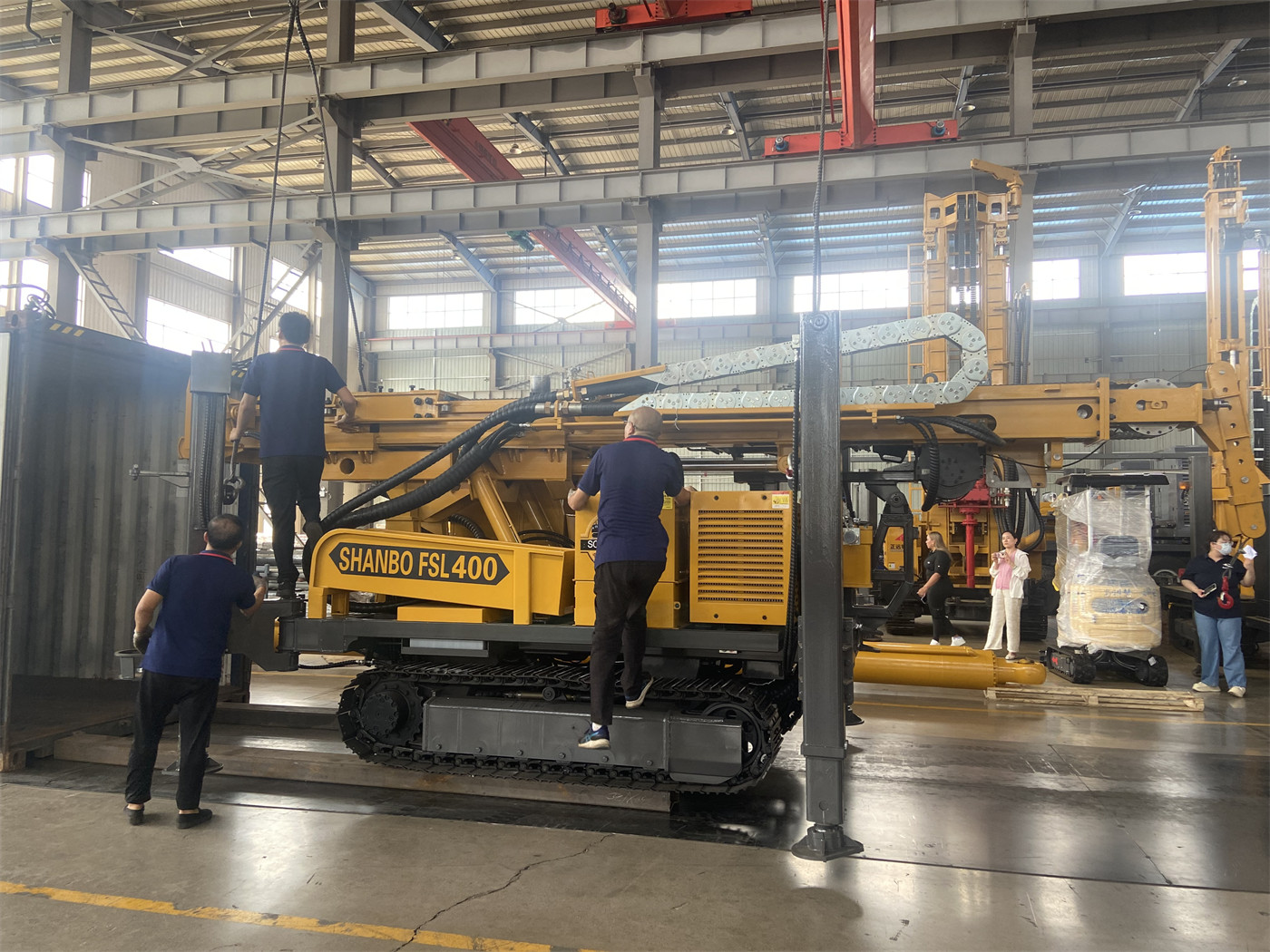
The wide range of hole diameters means the same equipment can handle mineral exploration holes as well as large-diameter deep water wells and some mine dewatering. However, for anomaly verification, hole diameter selection should first be subordinate to the sampling process and drilling tool coordination, rather than being as large as possible. After the hole diameter is increased, the air volume and drill string load required at the same hole depth will change, and this needs to be checked together with the air supply conditions.
The sample return path determines whether samples can be used
RC drilling uses dual-wall drill rods. Compressed air travels down the outer channel of the drill rods, drives the RC hammer and bit at the hole bottom, and then carries cuttings back to the surface through the inner channel. Compared with ordinary outer annulus flushing, the inner tube sample return path is more concentrated, which helps reduce contact between samples and different hole sections and improves the operability of sampling by depth interval. This is one of the main reasons the RC method is considered in anomaly verification: verification requires cutting samples traceable by depth, not just advance.
Sample return continuity depends on multiple conditions being satisfied simultaneously. The information gives a recommended working air pressure of 1.6–6 MPa and an air consumption of 16–75 m³/min. 600-meter-class RC drilling not only needs to drive the downhole drilling tool but also needs to carry cuttings back to the surface over a long distance. As hole depth, hole diameter, altitude, and rock hardness increase, the required effective air volume usually also increases. On site, changes in sample return volume, particle size, color, and moisture should be continuously observed; if there is a sudden decrease in samples, delayed sample return, or obvious cross-contamination, the drill rod seals, sample return channel, air compressor output, and whether there is air leakage in the hole should be checked. This part belongs to the process and supporting conditions, and the rig itself is only one link.
Lifting force and torque: margin for drill string handling in deep hole sections
The RC600 has a lifting force of 29 T. As hole depth increases, the dead weight of dual-wall RC drill rods and the friction resistance of the hole wall both increase significantly. Greater lifting capacity is beneficial for normal tripping, drilling tool recovery, and some casing handling. The information also notes that if tripping resistance continues to be abnormal, the issue should be prioritized through hole cleaning and judgment of in-hole conditions, and it is not recommended to directly use maximum lifting force to pull forcefully. This boundary shows that lifting force is a handling margin, not a universal means of solving in-hole anomalies.
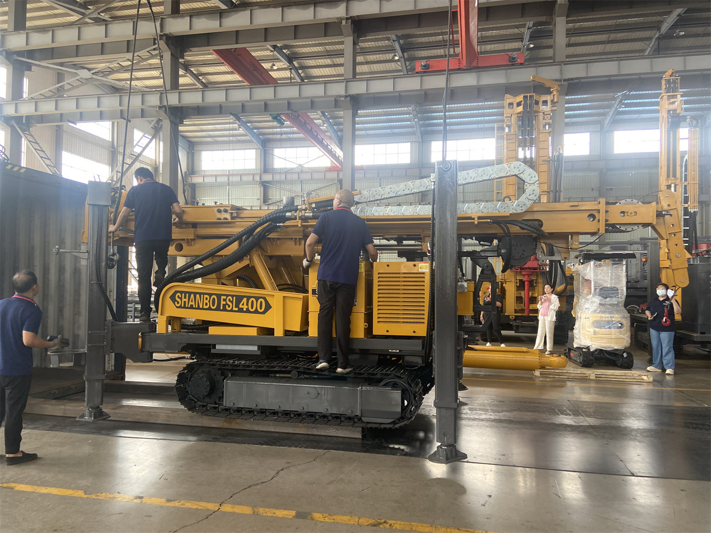
The rotary system has a maximum torque of 12000 / 6000 N·m, corresponding to maximum rotation speeds of 75 / 150 r/min. Low speed and high torque are suitable for large-diameter, hard rock, and high-load hole sections, while the high-speed gear is suitable for stable formations with lower resistance. RC drilling requires simultaneous attention to rotation, percussion, and sample return status, and coordination among the three is more important than pursuing any single parameter alone.
Drilling angle: the direction of the verification target body is more critical than depth
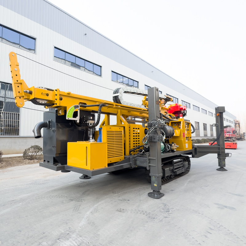
The equipment supports working angles of 45° and 90°. 90° can be used for conventional vertical exploration and water well construction, while 45° is more suitable for inclined crossing of inclined ore bodies, veins, and fault zones. For deep anomaly verification, a reasonable drilling angle is often more effective than simply increasing hole depth in approaching the target body; the angle should be determined according to the ore body attitude and exploration design, not by equipment default values. For 45° inclined holes, the force direction on the equipment is more complex, and the outriggers, ground bearing capacity, and overall levelness of the machine directly affect hole direction control and construction safety. The 1.7 m outrigger stroke in the information can be used for equipment leveling and stabilization, but site conditions still need on-site confirmation.
Supporting conditions: several constraints beyond the equipment
A 600-meter-class RC project cannot be completed with a drilling rig alone. The information mentions that projects usually also require a large air compressor, sample return hoses, sampling devices, and a sample area, and fuel, equipment locations, and maintenance space should be planned in advance on site. The overall weight is approximately 12.5 T, the dimensions are approximately 7 × 2.1 × 2.9 m, the crawler travel speed is approximately 3.5 km/h, and the maximum climbing angle reference is 21°. Before relocation, road bearing capacity, slope, and site stability should be confirmed.
| Operational need | Corresponding information condition | Still to be confirmed |
|---|---|---|
| Cover target body depth | Maximum drilling depth 600 m (typical configuration reference) | Target depth, final hole diameter, formation and hole deviation |
| Cross ore body at an angle | Working angle 45°/90° | Ore body attitude, site leveling conditions |
| Obtain cutting samples by depth | Dual-wall drill rod inner tube sample return | Sampling protocol, sample numbering and depth recording process |
| Deep hole drill string handling | Lifting force 29 T, torque 12000/6000 N·m | Drill rod specifications, in-hole friction, tripping resistance |
| Maintain sample return | Air pressure 1.6–6 MPa, air consumption 16–75 m³/min | Air compressor matching, altitude, hole diameter and rock formation |
Sample management and aspects not covered by the information
The equipment is responsible for obtaining samples, but final data quality also depends on sampling management. On site, samples should be collected at fixed advance intervals, recording hole number, sample number, start and end depths, and anomalous conditions; for mineral samples sent to the laboratory for analysis, duplicate samples, standard samples, and blank samples should also be set according to the project quality control system. These are project management matters, and the information only provides principle-level explanations; specific systems need to be determined by the project party.
The information shows that the RC600 supports RC drilling and conventional DTH hammer drilling, as well as mud rotary methods. Loose overburden may not be suitable for direct use of high-pressure RC drilling; mud rotary can first be used to stabilize the hole, and the process can be switched after entering stable rock. Broken zones and fractured formations are prone to hole wall collapse, air leakage, and abnormal sample return, requiring control of penetration speed and observation of air pressure changes. These process switching conditions are related to specific formations, and the information does not provide operating parameters for each formation; during selection, the formation column and hole structure should be used as inputs for separate confirmation.
There is another easily overlooked boundary: 600 m is an equipment capability reference value, not a depth that every anomaly verification project must reach. If the target body can already be controlled at a shallower position, continuing to deepen will only increase the burden of drilling tools, air supply, and sample management. Hole depth should be determined by the exploration design, and equipment capability is only one of the conditions for judging whether the design depth can be covered.