












At sites with dozens of continuously arranged exploration holes, geologists fear not difficult drilling but samples looping through the process: sample return suddenly decreases, requiring re-cleaning of the hole; after several transfers during splitting, the bags no longer match the depths; and after connecting rods and resuming drilling, one must judge whether this short segment counts as a transition sample. These actions generate no new footage but repeatedly occupy the rig, air compressor, and personnel. The problem this article addresses is: identify the steps in the sampling process prone to backtracking, and determine which can be linked at the equipment level and which can only be constrained by on-site management.
The discussion uses public information on the RC500-CS3 from this site as a reference. It is a 500-meter-class crawler-mounted reverse circulation drilling rig integrating the CS3 three-in-one cyclone sampling system, with a maximum drilling depth of 500 m, hole diameter of 105–400 mm, working angles of 45°/90°, and a 132 kW Cummins engine. The following content only explains parts supported by the information and does not replace the project's own sampling procedures.
Where the Three Main Backtracking Segments Occur
Assume a continuous sampling scenario (hypothetical for process illustration only, not an actual case): holes are sampled in fixed footage segments, and sample bags must be labeled with hole number, start and end depths, and number. Organized around this goal, backtracking steps concentrate in three segments.
- Sample return segment: Cuttings do not return stably through the inner tube, forcing the site to stop drilling, clean the hole, and re-establish circulation; the drilled footage must then be matched to a sample segment.
- Splitting segment: Samples are first piled on the ground, then manually split again, bagged, and transported, adding extra handling and waiting.
- Recording segment: Bag information cannot be matched one-to-one with on-site records, requiring backtracking to supplement records or even re-sample during later submission and archiving.
Among the three, the first relates to circulation method and air supply conditions; the second to how the sampling device is organized; the third is essentially a management issue—equipment can only facilitate, not make judgments for people.
Sample Return Segment: Which Path Is Shortened by Inner-Tube Return
Reverse circulation drilling uses dual-wall drill pipes to establish an independent sample return channel; cuttings mainly return through the inside of the drill pipe rather than up the annulus along the outer wall. The information states: this shortens the path along which samples contact other formations on the hole wall, helping reduce the probability of cuttings from different depths mixing.
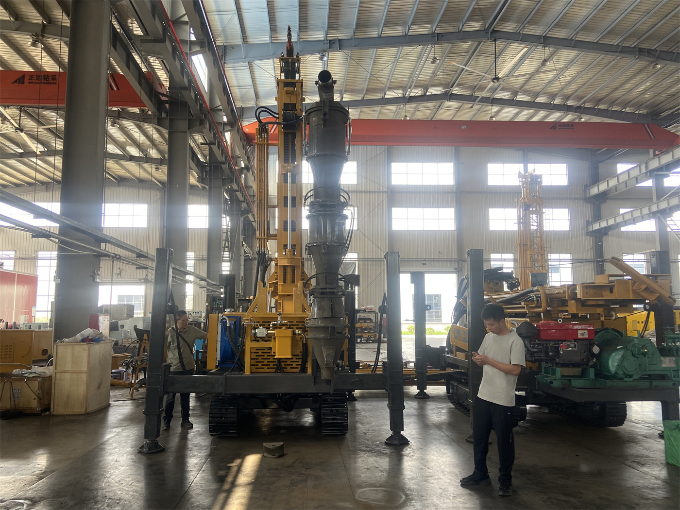
What this means for continuous sampling: the sample's travel path within the hole is relatively independent, and return stability depends more on whether air supply is continuous and whether rod connection and hole cleaning are performed properly. The information also clarifies that final sample representativeness still depends on hole cleaning, rod connection, return stability, and on-site sampling management—that is, inner-tube return reduces mixing risk along part of the path but does not automatically guarantee each sample matches its depth.
Whether return can be stabilized also depends on air supply. RC500-CS3 information gives recommended working pressure of 1.6–6 MPa and recommended air consumption of 16–55 m³/min. During 500-meter-class RC drilling, the air compressor must both drive the down-the-hole hammer and carry cuttings at high speed from the inner tube to the surface. Actual selection should consider hole diameter, RC hammer specifications, altitude, and rock hardness—the information provides no corresponding table for these conditions, so they must be confirmed separately before mobilization and cannot be inferred solely from drilling depth.
Splitting Segment: Which Actions the Three-in-One System Links
The CS3 system information describes integrating cyclone separation, representative splitting, and sample collection in one device: cuttings return to the surface through the inner tube of dual-wall RC drill pipes and enter the cyclone system directly, where high-speed airflow is separated from solid particles, and then a splitting mechanism forms samples usable for geological records and assays.
Corresponding to the backtracking steps listed earlier, this structure reduces repetitive operations in ground transfer and manual splitting, making it more suitable for continuous exploration holes and large-volume sample collection tasks. The information also mentions that the three-in-one system can reduce manual sample pouring, secondary splitting, and repeated handling.
Boundary to note: this is a process connection, not a precision guarantee. The information does not provide splitting precision, sample representativeness verification methods, or split effects under different lithologies; these should be confirmed separately with the manufacturer. In addition, sample bags and operating areas are usually arranged near the device; when using lifting aids (the 1.5 T auxiliary winch is for handling drill tools and sampling accessories), suspended loads should be kept out of the sampling personnel's work area.
Recording Segment: What Equipment Can Provide and What Management Must Supplement
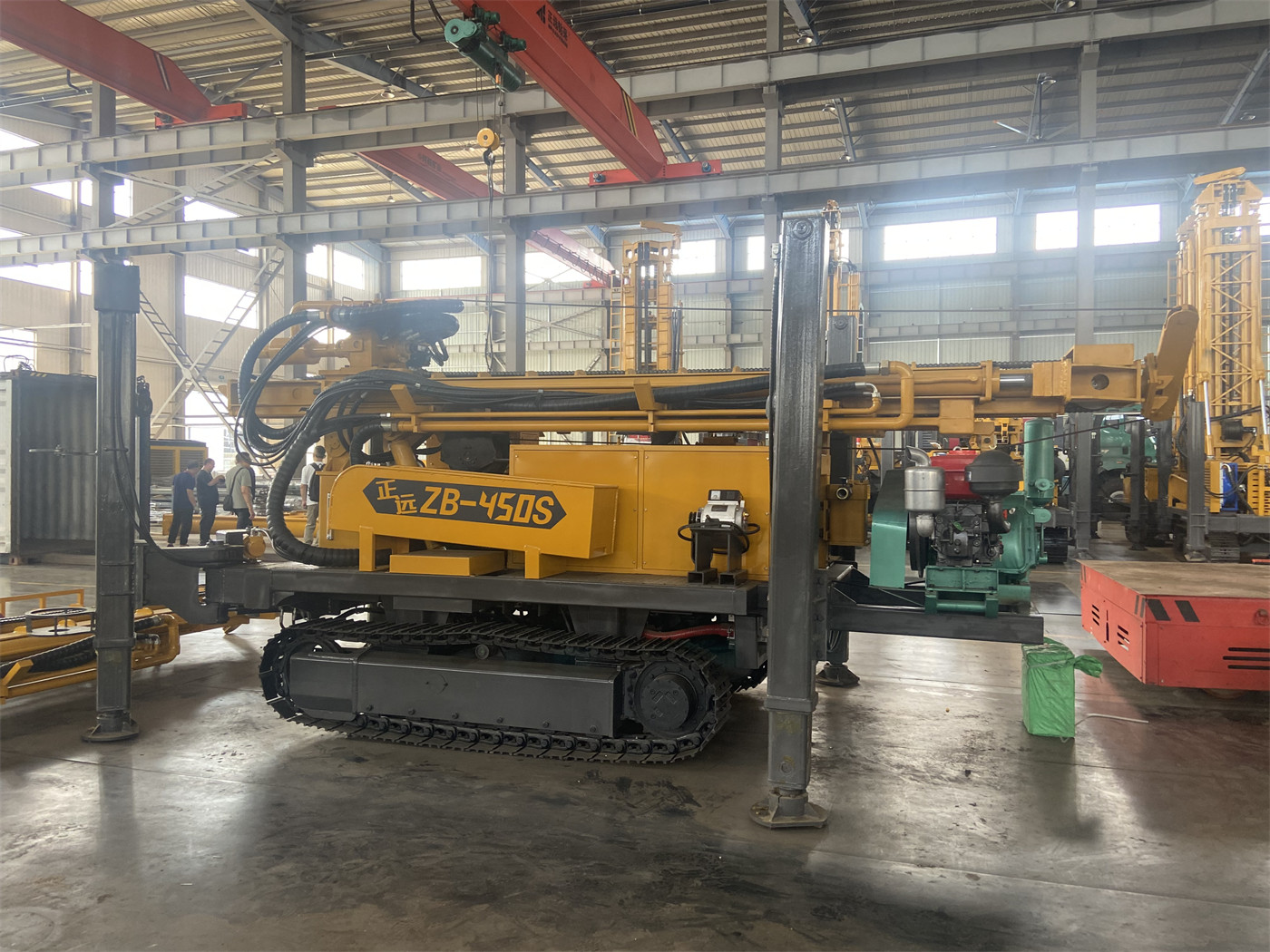
The information is clear: each sample bag can be labeled with hole number, start and end depths, date, and sample number for later submission, archiving, and traceability; on-site records should correspond one-to-one with sample bags; and ore samples sent to the laboratory should also include duplicate, blank, and standard samples per project quality control requirements. These are requirements at the sampling procedure level that equipment information cannot replace.
An easily overlooked downhole condition: in fault fracture zones, breccia, and fractured formations, wall collapse may temporarily remain in the hole and then return in a concentrated burst, affecting the correspondence between samples and depths. In such hole sections, the information recommends controlling penetration rate and maintaining stable air supply, with geologists adding on-site records and, if necessary, separately noting sample quality. This is a "judgment point" that must be reserved in the process, not something equipment can automatically eliminate.
The Short Segment During Rod Connection and Drilling Resumption
Another often underestimated point at continuous sampling sites: how to handle transition samples when resuming drilling after rod connection, hole cleaning, or stopping. The information requires handling transition samples according to on-site sampling procedures to avoid mixing residual cuttings from the previous hole section into the next depth sample.
The weight of this requirement lies in determining whether each hole section start needs separate judgment and labeling. If the sampling procedure does not specify this in advance, the site must discuss it ad hoc each time—which is itself a form of backtracking. Whether to set transition samples and how to label them are part of the project sampling plan; the information does not provide a uniform practice.
Which Hole Sections May Require Stopping to Switch Methods
The information mentions that upper soil, clay, sand, and gravel layers may not be suitable for direct RC pneumatic drilling; the model also supports mud rotary drilling, allowing upper hole sections to be stabilized with mud and casing before switching to reverse circulation or DTH in rock.
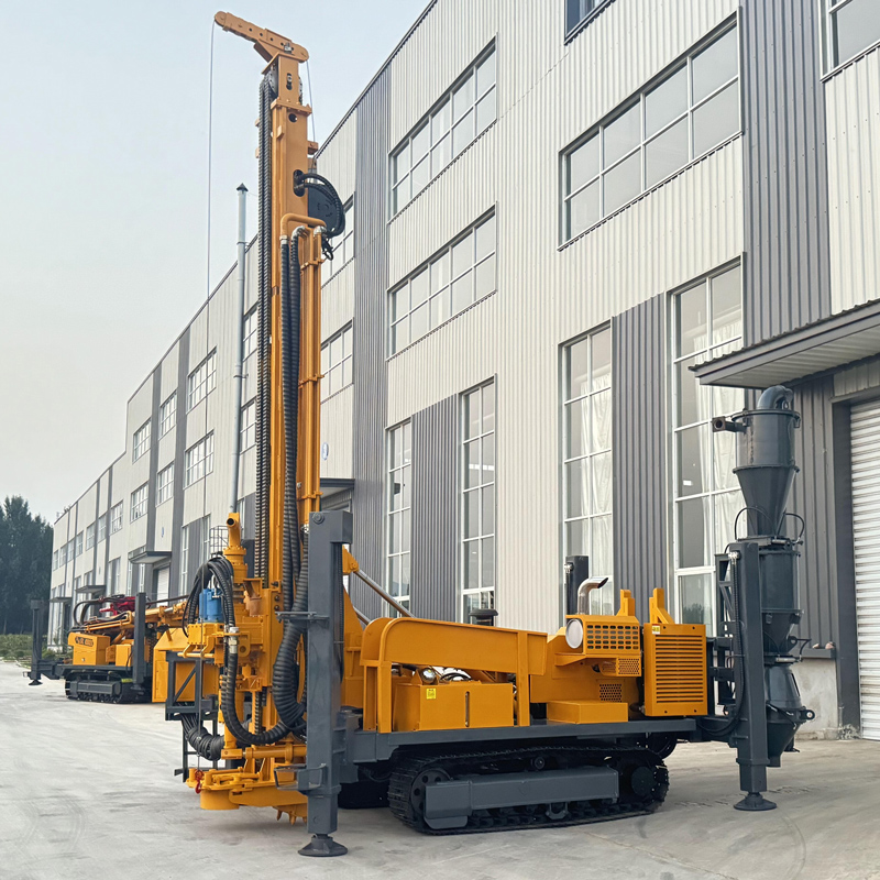
The impact on continuous sampling: if the overburden above a hole is thick, each hole may undergo a method switch, and depth records and sample connections at the switch point must be specified in advance. The basis for this judgment is the geological column and overburden conditions; the information does not provide recommended switch depths.
Relationship Between Equipment Capability and Process: Several Values to Read Together
The following parameters are cited only to explain process constraints, not as a basis for selection ranking.
| Information Item | Value | Significance for Continuous Sampling Process |
|---|---|---|
| Maximum drilling depth | 500 m | Determines the vertical range a single hole can cover, extending the sample depth intervals accordingly |
| Hole diameter | 105–400 mm | Hole diameter, RC hammer specifications, and air consumption constrain each other |
| Working angle | 45°/90° | Inclined holes for dipping ore bodies; determine according to geological section before collaring |
| Lifting force / feed force | 25 T / 7 T | Margin for tripping and pipe handling at 500-meter-class depths |
| Rotary torque / speed | 10000 / 5000 N·m; 75 / 150 r/min | Dual modes correspond to larger-diameter high-load and lower-resistance hole sections |
| Overall weight / travel speed | Approx. 12 T; approx. 2.5 km/h | Check road load capacity and platform area before moving between holes |
These values do not answer whether the process can reduce backtracking; they constrain the premises for process execution: depth and diameter determine how many sample segments each hole requires, lifting force and torque determine the smoothness of tripping, and overall weight determines how to move between holes. The information's note that drill pipe weight and wall friction increase with depth also suggests that abnormal pulling resistance should first be addressed through hole cleaning and process judgment, rather than directly relying on maximum lifting force to pull the drill string.
Items to Confirm Before Mobilization
- Select the air compressor based on hole diameter, RC hammer specifications, altitude, and rock hardness, not solely inferred from drilling depth; 1.6–6 MPa and 16–55 m³/min are only recommended ranges.
- Splitting precision, sample representativeness verification methods, and split performance under different lithologies are not provided in the information and must be confirmed with the manufacturer.
- Rules for transition, duplicate, blank, and standard samples are part of the project sampling procedure and should be documented before work begins.
- Methods for labeling sample quality in fracture zones and fractured formations should be agreed in advance with geologists.
- Site area should be planned together for the rig, air compressor, cyclone splitting device, sample bags, and transport vehicles; overall dimensions are approximately 7 × 2.1 × 2.9 m, and 12 T weight imposes requirements on roads and platforms.
- Whether to use mud rotary pre-drilling for upper overburden, and the switch depth, should be determined based on geological data; the information provides no recommended value.
- Whether 45° inclined holes are necessary should be judged by ore body attitude and geological section; determine the drilling angle before formal collaring.
Returning to the initial question: to reduce backtracking in continuous exploration hole sampling, three things must hold simultaneously—stable sample return channels, fewer handling steps in splitting, and depth records that match from the moment of drilling. The public information on the RC500-CS3 provides corresponding structural descriptions for sample return method and splitting connections, but it does not cover splitting precision, transition sample procedures, or specific judgments for formation switching. These parts must still be supplemented by the project's sampling plan; equipment only connects the steps that can be connected.