












Before starting a large-diameter foundation hole, the site often first decides "which drilling rig to use" and then makes the drilling tools accommodate the equipment. A more reliable order is the reverse: first determine the final hole diameter, hole depth, and formation, then verify whether the drill pipe length and diameter can fit this machine, whether the lifting force and rotary torque cover the drilling tool assembly, and finally determine the drilling method. This article is organized around this verification sequence, using the published data of the FR800 crawler foundation drilling rig as a reference, and explains what each step's data can answer and what must be confirmed back on site.
Step 1: Hole diameter determines the bit and also sets the lower limit of drill pipe diameter
Foundation hole design drawings usually give the opening diameter and final hole diameter, which may differ. FR800 data specifies a drilling diameter of 200–600 mm. This range does not mean any hole diameter can be drilled directly; the bit, drill pipe, and drilling method must match together. During verification, first write down the final diameter, then check whether the minimum opening diameter falls within the equipment range; if the design uses staged reaming, also list each stage's diameter and corresponding bit.
Drill pipe diameter and hole diameter are a matching relationship, not the same thing. FR800 recommends a drill pipe diameter of 89–245 mm. As hole diameter increases, the requirements for the cuttings discharge channel and drilling tool rigidity are higher, and the drill pipe diameter usually increases accordingly, but the specific grade to choose must be combined with bit specifications, formation, and drilling method. The data does not provide a correspondence table of "a certain hole diameter must use a certain drill pipe diameter," so this step can only confirm that candidate drill pipes fall within the recommended range; the final assembly must be verified with the drilling tool supplier.
Step 2: Consider hole depth and drill pipe length combinations together
The FR800 maximum drilling depth is 100–800 m, and drill pipe lengths are available in three configurations: 3 m, 6 m, and 9 m. Hole depth determines the total drill string length and the number of pipe connections, while drill pipe length determines whether a single pipe can match the power head stroke and mast structure. The combination of a 9.6 m power head stroke and 9 m drill pipe affects the coverage of one stroke during pipe connection, rather than directly increasing drilling depth capability.
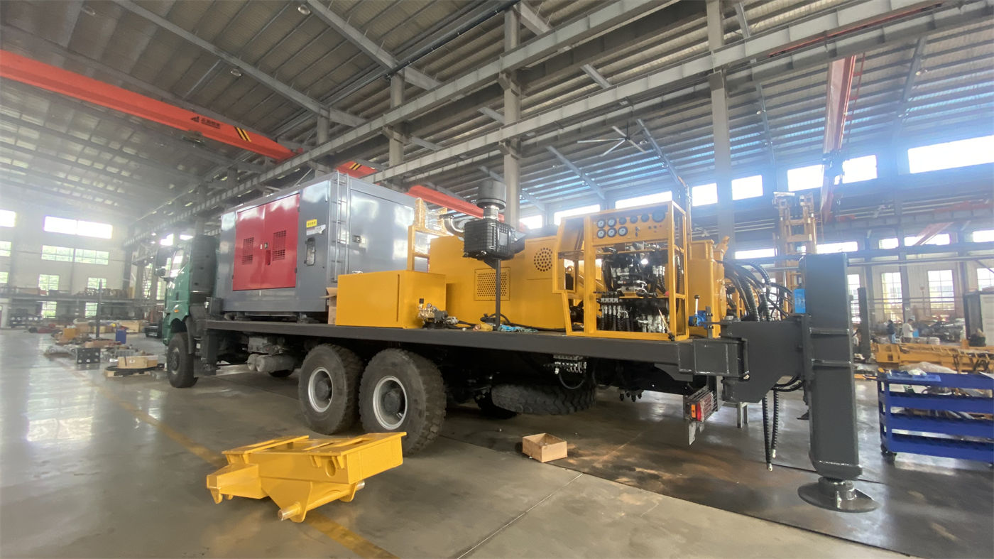
When verifying hole depth, the design hole depth, expected final depth, and possible over-depth allowance should be recorded separately. The 100–800 m in the data is a range value; the actually achievable depth is affected by formation hardness, hole diameter, drilling tool configuration, and construction process, and 800 m cannot be treated as a guaranteed value achievable at any hole diameter. If the design hole depth is close to the upper limit of the range, the hole diameter, drill pipe assembly, and drilling method should be submitted to the manufacturer for confirmation together.
Step 3: Which operation segment do lifting force and rotary torque correspond to?
The FR800 lifting force is 40 T, maximum rotary torque is 17600 N·m, and maximum rotary speed is 20–60 r/min. These three values constrain tripping of drilling tools, rotary rock breaking, and speed selection, respectively. Lifting force relates to the margin for pulling drilling tools in deep hole sections and handling downhole resistance; rotary torque relates to the rock-breaking capability of the bit in loose layers or bedrock; speed relates to bit type and formation.
During verification, it is not appropriate to look at any single item alone. In large-diameter hole sections, the weight and friction of drilling tools increase, so lifting force and torque should be evaluated under the same set of drilling conditions. The data does not provide recommended drilling tool weight or torque distribution for different hole diameters and depths, so it can only confirm that the equipment parameters cover the candidate process; it cannot be used to infer that a specific hole location will necessarily proceed smoothly. If downhole conditions are complex, the drilling tool assembly, expected friction, and pulling requirements should be included in the items to confirm with the manufacturer before drilling.
Step 4: Different drilling methods require different supporting checklists
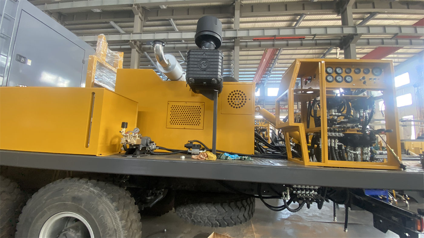
The FR800 supports three methods: hydraulic rotary, DTH hammer, and mud drilling. The three methods correspond to different supporting conditions and must be prepared separately according to the selected method before drilling:
- Hydraulic rotary drilling: mainly verify the bit and drill pipe assembly, and whether the power head torque and speed are suitable for the target formation.
- DTH hammer drilling: the data clearly states that an air compressor and DTH drilling tools matching the hole diameter, depth, and formation must be selected; for hard rock projects, the hammer specifications and air compressor parameters must also be confirmed.
- Mud drilling: the data states it is suitable for loose layers, collapse-prone formations, or projects requiring mud wall protection, and requires proper configuration of the mud pump, drilling tools, and circulation system; for different hole depths and diameters, the mud pump selection must also be verified accordingly.
These three methods are not interchangeable buttons; when switching, the supporting equipment, drilling tools, and site layout must all change accordingly. The data does not provide the air compressor displacement, pressure, or specific mud pump models corresponding to each method; these are supporting parameters that require separate confirmation.
Step 5: Site and entry conditions cannot wait until the equipment arrives
The FR800 overall weight is 25 T, travel speed is 2.5 km/h, and overall dimensions are listed in the data as 7600-5900×2300×2780 mm, with a note that final dimensions are subject to the formal technical confirmation document. The high leg stroke is 1.7 m, which involves equipment deployment space. Before drilling, the site bearing capacity, transport conditions, and equipment deployment space should be confirmed. These are listed in the data as items to confirm before entry, but no specific bearing values or transport limits are given, so they must be separately verified according to on-site measurements and the transport plan.
Put the verification items into one table
| Verification item | Data basis | Content to confirm |
|---|---|---|
| Final hole diameter | Drilling diameter 200–600 mm | Whether within range, whether staged reaming is used |
| Drill pipe diameter | Recommended 89–245 mm | Matching assembly with bit and drilling method |
| Hole depth and drill pipe length | 100–800 m; 3/6/9 m | Total drill string length, number of pipe connections, mast and stroke coordination |
| Lifting and rotation | 40 T; 17600 N·m; 20–60 r/min | Drilling tool weight, friction, formation-related margin |
| Drilling method support | Hydraulic rotary, DTH hammer, mud drilling | Specific specifications of air compressor, mud pump, and drilling tools |
| Site and transport | 25 T; 2.5 km/h; dimensions to be confirmed | Bearing capacity, transport conditions, deployment space |
The purpose of this table is to break "whether the equipment can do the job" into "which item is supported by data and which item still needs to be asked about." Hole diameter and drill pipe diameter have clear ranges and can be compared directly; drilling tool assembly, supporting equipment specifications, and site bearing capacity are not covered by the data and require joint confirmation by the project party and the supplier.
Applicable boundaries and items to be confirmed
The FR800 data is intended for building pile foundations, bridge foundations, mining engineering, and other large-diameter drilling projects, and the applicable formations are loose layers and bedrock. The data also states that actual drilling depth and construction efficiency are affected by formation hardness, hole diameter, drilling tool configuration, and construction process, and the 200–600 mm range must be matched according to the specific drilling method, drill pipe, and drilling tool assembly. Therefore, the above verification sequence can help place pre-drilling issues in the right categories, but it cannot replace drilling tool design and supporting confirmation for specific hole locations.
If a project involves hole locations with multiple diameters and depths, it is recommended to verify by hole location group rather than using one set of parameters to cover all holes. The data does not provide a correspondence table of recommended drill pipe diameters for different hole diameters, air compressor or mud pump selection parameters for each drilling method, or specific limits for site bearing capacity; these should be raised separately during the inquiry and entry preparation stages. The final step before drilling is to list confirmed items and items to be confirmed separately; before the items to be confirmed are resolved, they should not be treated as "matched."