












Pile positions in mountain PV sites rarely lie on the same plane. Within the same row of mounting structures, left and right pile positions may differ in height by tens of centimeters, while front and back pile positions are offset as the slope undulates. Where the equipment can stand and whether the drilling tool can reach the pile position often become on-site problems earlier than whether the machine can drill at all. This article addresses a decision-sequence question at the selection stage: when slope undulation is significant, which conditions should be checked first before evaluating the equipment's high-low legs and posture adjustment capability, so that "adjustable track height" is not treated as an isolated selling point.
First, determine what challenges the slope presents to the equipment
The impact of slope undulation on PV pile driving equipment can be divided into three levels. The first level is equipment positioning: with the tracks resting on the slope, the ground contact height on the left and right sides differs, and the machine must maintain a workable posture. The second level is pile position alignment: once the chassis is stable, the drilling tool must be able to reach the pile position laterally, front-to-back, and in angle. The third level is the drilling itself: whether the hole diameter, hole depth, strata, and drilling tool configuration match.
These three levels must be assessed in order. If the positioning conditions are not met, even the largest posture adjustment range is merely a forced compromise. If the pile position deviation exceeds the adjustment range, it must be compensated by repositioning the machine or leveling the ground, and no matter how impressive the equipment specifications are, they will not translate into construction productivity. Therefore, when selecting equipment, asking about the slope first, then the pile position, and finally the drilling is more relevant to mountain sites than looking at hole diameter and torque first.
First check: left-right elevation difference and track ground contact
Public information on the PV390H states that the track height telescopic dimension is 1200 mm, and the track height can be adjusted according to slope gradient to handle relatively significant left-right elevation differences. This figure answers "within what range the equipment can adjust the height of the two tracks," not "whether the slope is necessarily safe if the elevation difference falls within this range." The information also states that the high-low leg function cannot replace a safe construction platform and foundation bearing capacity assessment; cross-slope construction should be approached with greater caution, and the equipment should be ensured to be at low speed or stopped before adjusting track height.
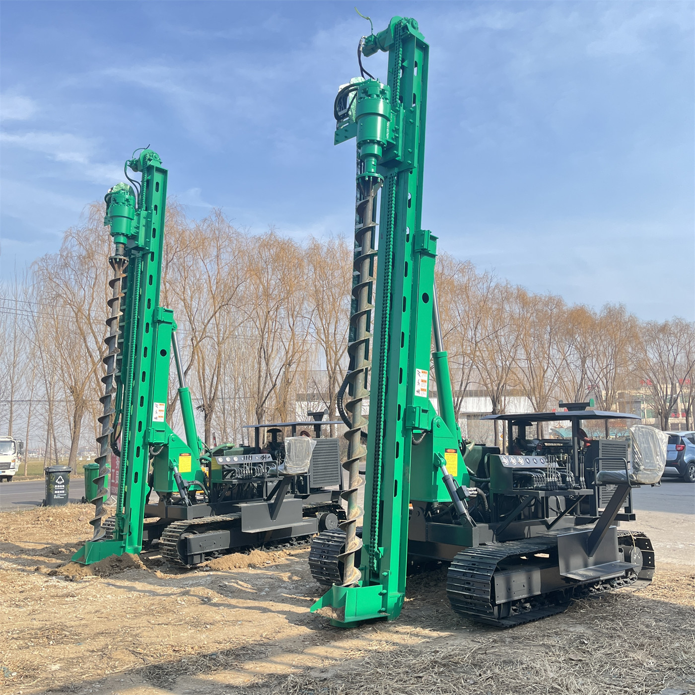
Therefore, this step should be broken down into several specific questions: What is the approximate magnitude of the left-right elevation difference on the slope? Is the ground at the track contact area undisturbed soil, backfill, or gravel? Will the adhesion conditions change after rain? Will the equipment be traveling on the slope or working at a fixed point? The 1200 mm is an adjustable range; whether it can be used on site depends on ground bearing capacity, center of gravity, and operating method. The information does not provide specific slope limits, which need to be confirmed separately according to project conditions.
Second check: which mechanism covers the pile position deviation
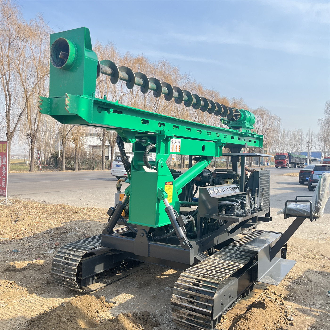
After the equipment is stabilized, pile position deviations are usually not in a single direction. The adjustment capabilities listed in the PV390H information each cover different directions: the 120° mast pitch handles drilling angle and posture differences caused by the slope; the dual-cylinder left-right swing arm handles lateral deviation; the 450 mm telescopic compensation handles fine front-back adjustment; and the track height adjustment handles left-right elevation differences at the chassis level. The information also notes that when these mechanisms work together, they are better suited to PV foundation projects with dense pile positions and frequently changing ground elevation differences.
| On-site deviation direction | Corresponding adjustment mechanism | Range given in the information |
|---|---|---|
| Left-right elevation difference | Track height telescoping | 1200 mm |
| Drilling angle and slope posture | Mast pitch | 120° |
| Lateral pile alignment | Dual-cylinder left-right swing arm | Swing angle value not given in the information |
| Front-back fine adjustment | Telescopic compensation | 450 mm |
The purpose of this table is to break "pile alignment" into several actions that can be checked separately. When selecting equipment, the questions to ask are: In which direction do pile position deviations mainly occur in this project? Is the range of the mechanism corresponding to that direction sufficient? When it exceeds the range, what is used on site to compensate—repositioning the machine, leveling the ground, or adjusting the pile layout? The information does not provide the lateral swing angle value of the swing arm, nor does it provide the effective pile alignment radius at a specific slope gradient; this part cannot be directly inferred from the existing parameters.
Third check: whether power, hole diameter, and hole depth cover the operation itself
Only after the posture conditions are met does drilling capability come into play. The PV390H is equipped with a 130 kW Yuchai six-cylinder turbocharged engine, a reducer torque of 13000 N·m, a drill pipe rotation speed of 100 r/min, a drilling diameter of 80–600 mm, a drilling depth of 0–6 m, and chain feed. The information states that larger hole diameters, dense soil layers, and gravel-containing conditions require higher rotary torque; when encountering cobblestone, backfill layers, and strongly weathered rock, the feed speed should be controlled according to the rotary load.
These parameters correspond to the operational goal of pre-drilling for PV mounting structures and pilot holes for pile positions, not water well drilling. The information explicitly states that the core value of the PV390H is not deep-hole capability but high-frequency pile position construction, adaptability to complex slopes, and rapid pile alignment. Therefore, when assessing, the 6 m hole depth and 600 mm hole diameter should not be treated as a combination that can simultaneously hold at full load; the specific hole diameter, hole depth, and drilling tools should be determined according to the project foundation design. After replacing with impact drilling tools, it can be used for strongly weathered rock and rock layers, but the information does not provide the impact hammer model and impact energy, so hard rock efficiency cannot be concluded from the existing content.
Fourth check: whether site access conditions are within the equipment's capability
The PV390H uses a crawler chassis with a track shoe width of 300 mm and overall dimensions of 5200 × 2300 × 2800 mm. The information states that it is suitable for PV pile foundation construction in mountainous and hilly areas and can be used on dirt roads, grassland, gravel ground, and general slopes, but in wet and slippery slope areas, soft soil, and areas with large cross-slopes, speed should still be reduced and rollover risk monitored. The information also mentions that after adding a winch, it can be used for steeper slope conditions, but before use, the anchor points, wire rope, and traction direction must be confirmed to be reliable; the winch cannot replace necessary construction roads and safe platforms.
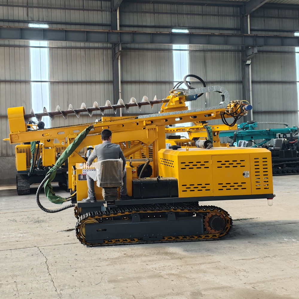
This step should be incorporated into site entry planning: Can the construction access road support crawler equipment? How long is the transfer distance? Will the slope soften during the rainy season? Is frequent short-distance movement between pile positions required? Compared with wheeled equipment, crawler chassis are more suitable for short-distance transfers within the site—this is the comparison direction given in the information—but the specific accessibility of a given site still needs to be verified against road width, slope gradient, and foundation conditions.
Putting these checks back into the selection sequence
Connecting the above, the decision sequence for high-low leg equipment on undulating mountain slopes is roughly as follows: first confirm whether the slope elevation difference and track ground contact are within a controllable range; then confirm whether the direction and magnitude of pile position deviation fall within the coverage of the posture adjustment mechanisms; then verify whether the hole diameter, hole depth, strata, and power torque match; and finally check the access road, transfer, and auxiliary traction conditions. At each step, there may be items where "information is insufficient and on-site confirmation is needed," which are precisely the items that should be clarified one by one with the manufacturer and project owner during the selection stage.
- The magnitude of the left-right slope elevation difference and ground contact conditions: the information does not provide slope limits; on-site verification is required.
- The actual coverage range of the swing arm for lateral pile position deviation: the information only states dual-cylinder left-right swing arm and does not provide the swing angle value.
- How to select drilling tools for the target hole diameter and hole depth combination: confirmation is required according to the foundation design.
- The impact drilling tool model and efficiency for strongly weathered rock and rock layers: not covered in the information.
- The anchoring scheme for winch-assisted traction is an on-site safety condition and cannot be replaced by equipment parameters.
The PV390H's high-low legs, 120° mast pitch, dual-cylinder swing arm, and 450 mm telescopic compensation address precisely the two categories of problems: slope positioning and pile position alignment. The 130 kW power, 13000 N·m torque, 80–600 mm hole diameter, and 0–6 m hole depth address the drilling conditions for shallow PV foundation pre-drilling. Whether it is suitable for a specific site does not depend on any single parameter but on whether each condition in the above decision sequence can be satisfied simultaneously. The slope limits, swing arm angle, and hard rock efficiency not covered in the information should be raised separately as items to be confirmed during the selection stage.