












In equipment discussions about photovoltaic foundation pre-drilling, 13000 N·m and 0–6 m are often written on the same parameter table row, reading like two parallel "capability indicators." On the pile-position site, however, they do not constrain the same thing: torque determines whether the drilling tool can maintain rotation when encountering resistance in the hole, while hole depth determines how far the drilling tool can travel axially and how deep a pile foundation design it can cover. Conflating the two easily leads to judgments divorced from reality, such as "if the torque is large enough, it can drill any stratum" or "if the hole depth is only 6 m, it can't do the job." This article addresses exactly this reading problem: first distinguishing which operational stage each figure governs, then examining which conditions in the PV390 materials pair with them and which still require on-site confirmation.
Torque Constrains the Rotation Stage, Not the Entire Hole
The PV390 materials give a reducer torque of 13000 N·m, a drill pipe rotation speed of 90 r/min, and chain pressurization. This set of figures corresponds to the rotation and advancement stage of the drilling tool within the hole, not the entire process from hole alignment to hole completion. When hole diameter, stratum, or drill bit type changes, the same torque faces different resistance: in dense soil layers or strata containing gravel, rotational resistance rises, and torque is the direct condition for maintaining the drilling tool's continued rotation; in soil layers and loess where resistance is relatively low, torque margin is more about whether it can hold steady when encountering local hard layers rather than daily penetration speed.
It should be noted that the materials do not provide actual penetration data under different strata, nor do they directly correlate torque with construction results in any particular type of stratum. Therefore, what 13000 N·m indicates is the equipment's configuration at this level of rotational capability; it cannot be used to infer the hole-forming speed or quality at any specific site.
0–6 m Constrains the Drilling Tool Stroke and Pile Foundation Depth Coverage
The materials specify a drilling depth of 0–6 m and clearly position this model for photovoltaic pile foundations and shallow foundation projects, not deep water well construction. This figure corresponds to the maximum axial stroke range of the drilling tool along the hole, answering "whether this type of pile foundation depth falls within the equipment's coverage range" rather than "how fast this equipment can drill."
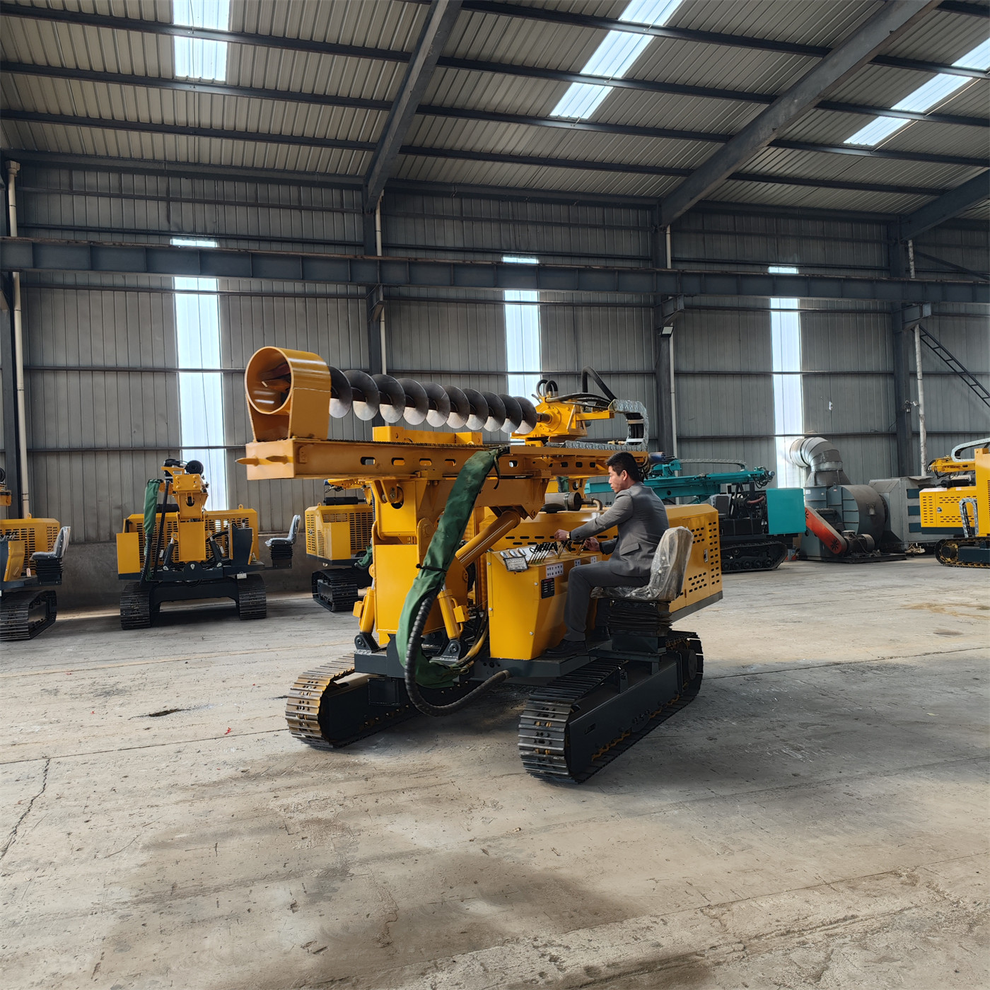
For conventional photovoltaic support foundations, fence posts, and other shallow foundation projects, the design depth typically needs to be checked item by item against this range: when the design hole depth approaches 6 m, the drill tool assembly length, rod connection method, and whether there is margin for bottom-hole cleaning must also be considered. The materials do not provide specific construction organization methods for different hole depths; this part needs to be confirmed at the project level according to design drawings.
Hole Diameter and Hole Depth Must Be Considered Together, Not Just One
The PV390 materials specify a drilling diameter of 80–600 mm and a drilling depth of 0–6 m. Only when the two figures are taken together do they define this equipment's operational envelope: hole diameter determines the lower limit of drill bit and drill pipe diameter, while hole depth determines the total length and stroke of the drilling tool. On the same equipment, large and small hole diameters face different discharge volumes and rotational resistance, and increased hole depth changes the drill string length and load conditions.
| Parameter | Material Value | Corresponding Operational Stage |
|---|---|---|
| Reducer torque | 13000 N·m | Maintaining drilling tool rotation within the hole |
| Drill pipe rotation speed | 90 r/min | Rotation speed setting |
| Drilling depth | 0–6 m | Drilling tool axial stroke and pile foundation depth coverage |
| Drilling diameter | 80–600 mm | Matching range of drill bit and drill pipe diameter |
| Pressurization method | Chain pressurization | Application of continuous advancement force |
The table only maps the values stated in the materials to their operational stages; it does not mean any single set of figures can stand alone as a selection conclusion. The final hole diameter and hole depth must be based on project design drawings and foundation type.
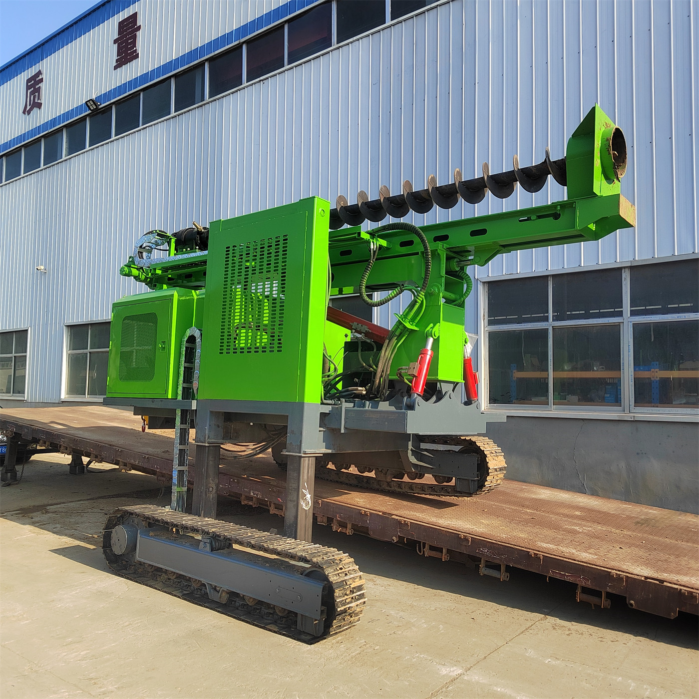
The Advancement Stage: Chain Pressurization Must Be Controlled According to In-Hole Load
Chain pressurization provides continuous advancement force applied to the drilling tool. The materials' description of stratum conditions notes that cobble sand and backfill debris layers may cause drill bit bouncing, hole deviation, jamming, and local voids; when abnormal impact or sudden increases in rotational load occur, the drill should be lifted promptly for inspection to avoid forced advancement. This section indicates that advancement and rotation require coordinated judgment rather than providing a fixed set of operating parameters. The materials do not give recommended advancement speeds or pressurization settings for different strata; how to control this on site is a matter of construction organization that needs separate confirmation.
The Hole Alignment Stage Is Handled by Mast Attitude Adjustment
Beyond torque and hole depth, photovoltaic pre-drilling has another motion directly related to the number of pile positions: after the equipment is stabilized, whether the drilling tool can quickly align to the pile position. The PV390 materials list 120° mast pitch, dual-cylinder left-right swing arms, and 50 cm fore-aft telescopic compensation, covering adjustment in three directions: angle, lateral, and longitudinal. These three mechanisms address hole alignment deviation after stopping, and do not change the capability boundaries of torque and hole depth themselves.
The materials also specify 400 mm track pads and a climbing angle of 35°. These are chassis passability conditions, a different set of indicators from drilling capability. For slope operations, whether the machine can actually hold position must also be judged based on cross-slope, ground wetness, soil conditions, and overall center of gravity; the maximum climbing angle in the materials cannot be directly used as a basis for safe travel.
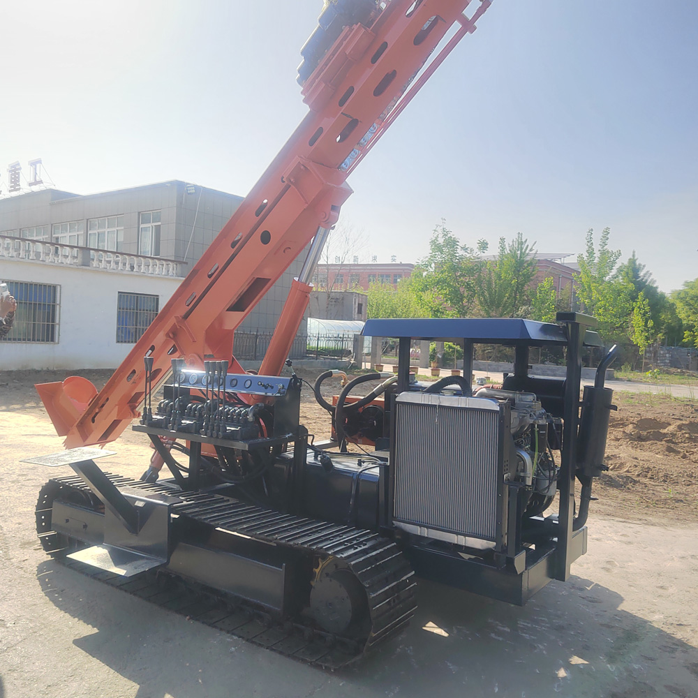
Stratum Conditions Are Stated in the Materials, but Conclusions Must Be Left to the Site
The PV390 materials list applicable geology including soil layers, loess, clay, cobble sand, and backfill debris layers, and note that after changing to impact drilling tools it can be used for strongly weathered rock and rock layer construction. The materials also note that the original data does not provide the impact hammer model or impact energy, and therefore no additional commitment is made regarding hard rock efficiency. This point is worth noting when reading the parameters: the stratum list describes which stratum types the equipment is described as being able to face, which is not the same as providing drilling performance in each stratum.
Items Still Requiring Confirmation Before Selection
- Whether the final hole diameter and hole depth of the designed pile type fall within the 80–600 mm and 0–6 m ranges, and how the drilling tool assembly should be configured when approaching the upper limits;
- Whether the project strata involve types not listed in the materials; if strongly weathered rock and rock layers are involved, the impact drilling tool model and supporting conditions need to be separately confirmed with the manufacturer;
- Cross-slope, ground adhesion conditions, and overall machine stability in slope areas cannot be judged solely on the 35° climbing angle;
- Power side: the materials specify an 85 kW Yuchai four-cylinder engine and a triple pump 40/40/32; during continuous high-load operation, inspection of cooling, air filter, and fuel system belongs to the usage stage, and the materials do not provide specific maintenance intervals;
- The model in the materials is PV390; the original data once showed an SL390 designation. The model should be based on the latest confirmation, and other parameters are organized according to the provided materials.
Returning to the opening question: 13000 N·m governs whether the drilling tool can maintain rotation within the hole, and 0–6 m governs the drilling tool's axial stroke and the pile foundation depth coverage range. Together with the 80–600 mm hole diameter, chain pressurization, and mast attitude adjustment, they constitute the operating conditions of this equipment in photovoltaic foundation pre-drilling. Which item is the limiting factor depends on the project's designed hole diameter, hole depth, and stratum combination—not on the numerical ranking of figures in the parameter table.