












Deep water supply well projects are often simplified into one question during the equipment inquiry stage: is the maximum drilling depth sufficient? But when it comes to actual construction organization, what determines whether a machine can be used is not just the drilling depth number, but how deep the target aquifer is, what hole diameter is required for well completion, how much weight the drill string must bear in the hole, which drilling process corresponds to the formation combination, and whether the entire machine can reach the hole location and be set up. This article focuses on this breakdown process, using the public information of WRT1200 as a reference, to explain which types of capability items the operational goals of a deep water supply well can be broken down into, which parameters in the information each item corresponds to, and what still needs on-site confirmation.
Item 1: Target aquifer depth corresponds to drilling depth reserve, not a construction depth target
The operational goal of a deep water supply well first falls on the aquifer location. The WRT1200 information gives a maximum drilling depth of 1200 m, suitable for deep groundwater, large-diameter water supply, and hard rock DTH drilling. This value should be understood as the upper limit of equipment capability, not that every project needs to drill to 1200 m. The target aquifer depth must first be determined by hydrogeological work, then judged whether that depth falls within the equipment's drilling depth coverage, with some margin left to handle downhole anomalies or deepened verification.
The information also explains that the 1200-meter-class depth reserve has practical significance only when shallow aquifers have insufficient water yield, mining areas need to find more stable water sources, or industrial projects require highly reliable water supply. In other words, the drilling depth item constitutes a selection reason only when the aquifer is indeed deep; if the project's target aquifer is at medium-shallow depth, the drilling depth reserve itself does not create operational value.
Item 2: Completed well diameter affects three types of loads: drilling tools, casing, and cuttings removal
The WRT1200 borehole diameter range is 105–900 mm, covering conventional deep water wells to large-diameter groundwater wells. Hole diameter is not an isolated design choice: a larger diameter facilitates the installation of larger well casing and submersible pumps, but the information also points out that increasing hole diameter simultaneously increases drilling tool load, casing weight, cuttings removal demand, and air compressor load.
Therefore, the completed well diameter item must be cross-checked in conjunction with other capability items. First determine a reasonable hole diameter based on water yield targets, well casing specifications, and pump type, then check back whether the equipment's lifting force, torque, and air supply conditions match at that diameter. The information does not provide specific drilling rates or single-well durations corresponding to a given hole diameter; this part needs to be separately confirmed in the construction design based on formation and drilling tool combination.
Item 3: Drill string and casing handling correspond to lifting force and auxiliary winches
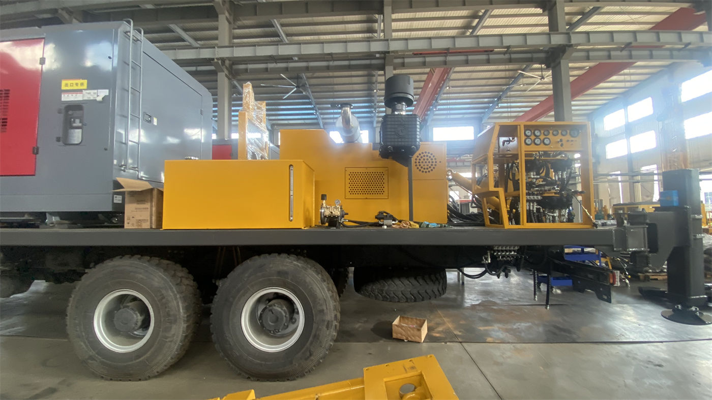
In deep hole operations, drill pipe dead weight, casing weight, and borehole wall friction increase significantly with hole depth. The WRT1200 information gives a lifting force of 61 T and a feed force of 13 T, and explains that higher lifting capacity facilitates deep hole tripping, DTH hammer recovery, and some casing operations.
Paired with the lifting force are dual auxiliary winches: a 4 T large auxiliary winch and a 3 T small auxiliary winch, which can be used for handling DTH hammers, drill pipes, casing, air hoses, and on-site accessories. 1200-meter-class projects have many drilling tools and heavy individual pieces; dual winches help reduce manual handling. However, the information also clearly states that if tripping resistance is abnormal, the hole should be cleaned first and the condition of the borehole wall, drilling tools, and sediment judged; one should not simply rely on maximum lifting force to pull forcefully. This means lifting force is a capability item for handling normal loads, not a universal means to solve downhole anomalies.
Item 4: Rotary torque has two ranges, corresponding to different hole section resistance
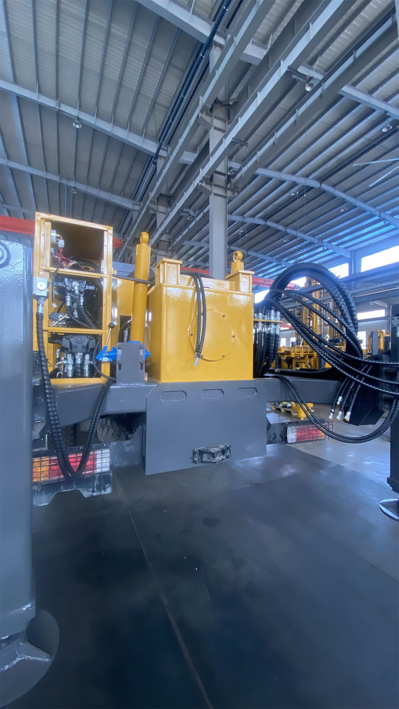
The WRT1200 rotary system has a maximum torque of 24000 / 12000 N·m, corresponding to a 75 / 150 r/min two-speed configuration. The information explains that low speed and high torque are more suitable for large-diameter, hard rock, and high-friction hole sections, while the high-speed range is suitable for stable formations with lower resistance. During construction, the operating condition should be switched promptly according to drilling tool load, cuttings return, and torque changes.
This item is often misread as "two speed gears" or "two-speed gearbox." In fact, the two torque values correspond to rotary capability choices under different hole section conditions, not a simple speed preference. Understanding dual-condition torque as speed gears that can be switched at will easily ignores the load borne by the low-speed high-torque range in large-diameter hard rock sections, and also easily underestimates the applicable boundary of the high-speed range in stable formations.
Item 5: Formation combination determines drilling process and air supply support
The WRT1200 information provides process connection ideas according to formation: upper loose layers can use mud rotary, casing, or other hole stabilization methods; intact hard rock can be equipped with medium and high pressure DTH hammers for DTH drilling; weathered rock and fractured zones should control penetration, strengthen hole cleaning, and use casing or foam assistance according to borehole wall conditions; after entering the main aquifer, the air supply, hole cleaning, and casing plan need to be adjusted according to water inflow.
During DTH drilling, the information recommends a working air pressure of 1.65–8 MPa and an air consumption of 16–120 m³/min, and specifically points out that merely meeting pressure while insufficient displacement can still lead to insufficient impact, difficult cuttings removal, and bottom-hole sediment accumulation. This item shows that air supply conditions are not a built-in equipment capability, but an external condition that requires air compressor support and must be calculated together with hole diameter, hole depth, and formation. The information does not specify which pressure and displacement range should be selected for a particular project; this needs to be confirmed in the construction design in combination with hole diameter and drilling tool assembly.
Item 6: Relocation method and overall transport conditions
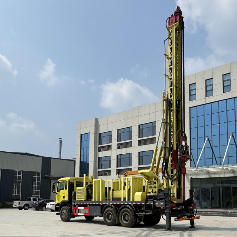
The WRT1200 adopts a truck-mounted straight mast structure, integrating the mast, power head, hydraulic feed, dual auxiliary winches, and operating system on a truck-mounted chassis. The information explains that this structure is more suitable for road relocation between mining areas, industrial parks, farms, and different cities, reducing repeated loading and unloading and lifting organization.
However, the cost of the straight mast structure is a more fixed transport profile. The overall weight is approximately 32 T, and transport dimensions are approximately 11.5 × 2.25 × 3.2 m. The information explicitly requires confirming road height limits, access space, and site clearance before construction; before access, road width, bridge load capacity, turning radius, site bearing capacity, and overhead obstacles must also be verified. This item corresponds not to equipment capability, but to whether the project site conditions allow the equipment to arrive and set up; if road or site conditions are not met, drilling depth and torque capability cannot be brought into play.
Putting the six capability items back into the same checklist
The above six items are not a parallel parameter list, but a judgment chain with sequential relationships: first determine aquifer depth and completed well diameter, then check drill string handling capacity and rotary torque, then determine drilling process and air supply support, and finally confirm whether the entire machine can access the site. If any item does not hold, it will change the equipment selection or construction plan.
| Operational Goal | Corresponding Information Item | Still to Confirm |
|---|---|---|
| Target aquifer depth | Maximum drilling depth 1200 m | Actual aquifer depth and depth margin |
| Completed well diameter | Borehole diameter 105–900 mm | Well casing, pump type, and water yield design |
| Drill string and casing handling | 61 T lifting force, 4 T + 3 T dual auxiliary winches | Drilling tool assembly weight and borehole wall friction |
| Hole section resistance | 24000 / 12000 N·m dual-condition torque | Switching timing and formation correspondence |
| Drilling process and air supply | Air pressure 1.65–8 MPa, air consumption 16–120 m³/min | Air compressor support and hole diameter matching |
| Site access and relocation | Overall machine approx. 32 T, transport dimensions approx. 11.5×2.25×3.2 m | Road height limits, bearing capacity, and site clearance |
Parts not covered by the information that require project-level confirmation
The WRT1200 information also mentions power options of 220 kW or 264 kW diesel engines, feed stroke 7 / 13 m, recommended drill pipe diameter 127 mm, and support for 3 m or 6 m drill pipe lengths. These configuration items need to be determined according to project load, site conditions, and construction organization; the information does not provide configuration recommendations for specific working conditions.
In addition, actual water yield, completed well water quality, cementing and water shut-off design, submersible pump selection, and other well completion aspects belong to the scope of hydrogeology and well completion design. The information only states that the equipment can be used for deep water supply and does not include specific parameters for these aspects. Beyond equipment selection, deep water supply well projects also need to complete hydrogeological evaluation and well completion structure design, and then confirm whether the equipment configuration matches accordingly.