












When reviewing the documentation for a towed water well drilling rig, the first things usually seen are the drilling depth, hole diameter, and rotation speed tables; however, which systems are mounted together on the chassis also determines what projects the equipment is suited to undertake. This article starts from the structural feature of an "integrated layout on a towed chassis," first explaining which types of operational problems it addresses, then drawing on publicly available WRTR600 information to explain why these layout choices affect project positioning, and finally listing the conditions not covered by the documentation that must be confirmed before mobilization.
First, what exactly is integrated on the chassis
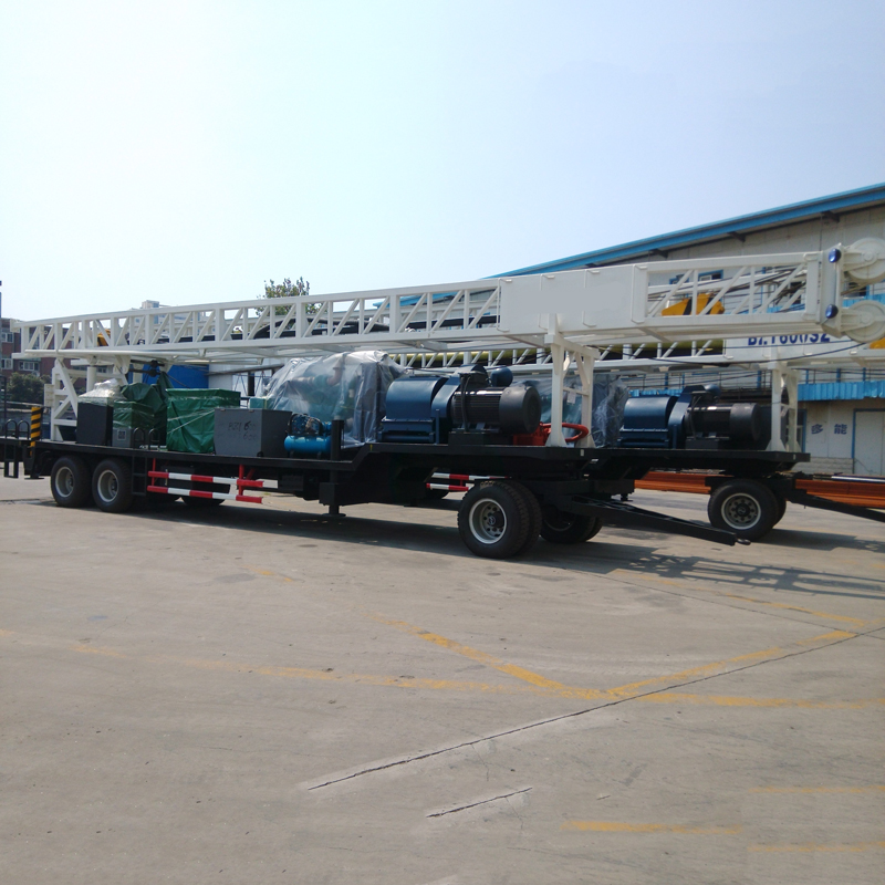
The publicly available WRTR600 information states that the equipment integrates the diesel generator, 3NB-130 mud pump, rotary table, double winch, mast, outriggers, and auxiliary breakout mechanism on a towed chassis. For site organization, this means the power source, circulation system, and hoisting and rotation mechanisms are not transported on separate vehicles and assembled on arrival, but are relocated and deployed as a single unit with the chassis.
The value of this layout lies not in any single parameter but in the waiting between process steps that it reduces: the wiring and piping between the power source and mud pump, the positioning of the mast and chassis, and the relative positions of the winch and rotary table are all determined at the factory layout stage, so on site the main tasks are towing into position, leveling the outriggers, raising the mast, and connecting the circulation lines.
Several types of operational objectives corresponding to the integrated layout
The typical applications listed in the documentation include deep water wells, geothermal wells, hydrogeological surveys, general geological exploration, and some foundation engineering boreholes. Viewing these uses in the context of the integrated layout makes it clear that this rig is positioned toward medium-to-deep hole operations that are "self-contained and capable of being relocated as a whole," rather than being dedicated equipment for a single process.
Remote hole locations without a stable power grid
The equipment integrates an SCGC-200kW diesel generator set, rated voltage 380 V, rated current 360 A, frequency 50 Hz, which can supply power to the mud pump, hydraulic oil pump, and auxiliary electrical equipment. For village and town water wells, agricultural irrigation wells, and remote geothermal survey sites, power availability is often the first issue to be resolved before mobilization; mounting the generator set on the complete rig is equivalent to incorporating the preliminary task of "where the power comes from" into the equipment itself.
The pump used for mud circulation and wall protection travels with the rig
The 3NB-130 mud pump has a specified displacement of 8.4–16.6 L/s and a rated working pressure of 5–10 MPa, driven by a 90 kW motor. Mud circulation carries drill cuttings, cools the drill bit, maintains borehole wall stability, and controls downhole pressure. In soil layers, clay, and soft overburden, mud viscosity needs to be adjusted according to formation permeability, hole diameter, and return flow conditions; in sand and gravel layers, temporary casing or staged casing installation should be considered. These processes all depend on the continuous availability of the pump and piping, and integrating them on the chassis reduces the on-site connection work among the pump, power, and piping.
Deep-hole rotation and drill string handling
The rotary table provides three speed ranges of 38 / 57 / 85 r/min, corresponding to theoretical torques of approximately 13.8 / 9.2 / 6.2 kN·m. The low-speed range offers higher torque, suitable for larger hole diameters, heavy drill strings, and formations with greater resistance; the higher speeds are suitable for stages with lower resistance. The main winch has a single-line pull of 40 kN, the auxiliary winch has a single-line pull of 30 kN, and the swivel has a maximum load of 30 T and an inner diameter of 63.5 mm. As hole depth increases, the self-weight of the drill string and borehole wall friction rise, and the matching among the swivel, winch, kelly, and drill pipe deserves more attention than the single-item hoisting capacity figures.
Different mast configurations mean different trade-offs in transport and efficiency for the integrated layout
This equipment is offered in short-mast and long-mast versions; the difference lies not only in height but also in transport dimensions and the number of pipe connections.
| Item | Short-mast version | Long-mast version |
|---|---|---|
| Effective mast height | 12 m | 15 m |
| Kelly | 108 × 108 × 7500 mm | 108 × 108 × 10500 mm |
| Drill pipe | Ø89 × 10 × 5500 mm | Ø89 × 10 × 9000 mm |
| Transport dimensions | Approx. 15100 × 2480 × 4100 mm | Approx. 16630 × 2480 × 4100 mm |
The short mast is more conducive to transport and site adaptability, while the long mast can reduce the number of pipe connections and improve continuous drilling efficiency in deep holes. This trade-off must be considered in light of the project itself: for projects with moderate hole depths, scattered sites, and ordinary road conditions, the short-mast version has a shorter transport length; for projects with greater hole depths and long continuous drilling time per hole, the process changes brought by fewer pipe connections with the long mast are more significant. Before cross-regional construction, regardless of version, road width, turning radius, bridge load capacity, height restrictions, and local towed-transport regulations should be confirmed.
From the perspective of project positioning, what conditions suit this equipment
Viewing the integrated layout together with continuous multi-site construction, the WRTR600 is positioned toward the following types of projects: village and town water supply and agricultural irrigation wells with relatively deep target aquifers and single-well hole diameters within 500 mm; remote geothermal surveys and medium-depth geothermal wells that lack a stable power grid and require self-contained power; and engineering drilling contractors with scattered hole locations who wish to relocate the entire equipment set as a whole.
Conversely, if a project only requires shallow holes, small diameters, concentrated well locations, and has good grid conditions, the overall weight and transport dimensions brought by the towed structure with integrated generator and mud pump may not be advantages, and other structural configurations should be compared instead.
Integration does not mean site conditions can be omitted
No matter how complete the equipment on the chassis, entry and deployment still depend on the site. The transport dimensions given in the documentation indicate a basic threshold for the complete rig on the road; whether it can actually pass through village roads, field ridges, bridges, and culverts must be checked section by section according to the towing vehicle and route. When raising the mast, confirm that there are no overhead lines or obstacles above; during mud circulation, pay attention to high-pressure lines, pump pressure, and leaks; personnel must not stand under suspended drill strings or near rotating drill strings.
Regarding formations, weathered rock and mixed soil-rock formations show pronounced changes in hardness; roller cone bits, drag bits, or other rotary drilling tools can be selected according to actual conditions, with adjustments to rotary table speed, torque, and mud pump displacement. Actual drilling depth and hole diameter are affected by formation, drilling tools, mud circulation, casing design, and downhole resistance; the 600 m and 500 mm figures in the documentation are equipment capability limits, not construction targets for every project.
Matters still requiring confirmation at the selection stage
- Road width, height restrictions, bridge load capacity, and towed-transport management requirements at the project location, especially whether the 16630 mm transport length of the long-mast version can pass.
- Target aquifer depth and well completion structure, used to determine whether the 600 m drilling depth and 500 mm rotary table through-hole cover the final hole design, rather than directly configuring to the upper limits.
- Drilling processes and mud programs corresponding to the formation combination, and whether loose layers require temporary casing or staged casing installation.
- If the project requires continuous high-quality cores, a dedicated core drilling rig should be considered separately; the WRTR600 documentation describes hydrogeological surveys and general formation drilling and does not cover continuous coring capability.
- Although on-site power is provided by the integrated generator set, fuel reserves, generator maintenance, and electrical system inspections still need to be included in mobilization preparations.
Integrated layout is an approach that moves process steps forward onto the equipment; what it changes is the number of on-site connection steps required at mobilization, not the downhole conditions themselves. When matching it to a specific project, it is still necessary to check well depth, hole diameter, formation, and entry route one by one.