












"Is 200-plus meters enough?" When inquiring about shallow-to-medium water well projects, this question usually gets a single drilling depth figure as the answer. But "sufficient" is not a single metric: for a machine to truly work on a given project, at least four things must hold true simultaneously—the target well depth falls within the drilling depth coverage, the completed well diameter falls within the borehole diameter range, the lifting force and rotary torque can handle the drill string at the corresponding hole depth, and the formation combination has a compatible drilling process. If any one of these does not hold, the drilling depth figure alone cannot answer the question.
This article addresses that judgment, using WR260's published specifications as a reference to explain what capabilities "sufficient" for shallow-to-medium water wells can be broken into, which parameter in the specifications each corresponds to, and which conditions the specifications do not cover and require project-level confirmation.
The first layer of "sufficient": target well depth and completed well diameter must both fall within range
WR260's specifications give a maximum drilling depth of 260 m and a borehole diameter of 140–305 mm. These two figures must be considered together. A target aquifer depth within 260 m only means the drilling depth item is not exceeded; the final hole diameter corresponding to the well casing and submersible pump configuration must also fall within the 140–305 mm range. When well depth approaches the upper limit and a larger diameter is selected, drill tool loads and cuttings removal conditions both change, so the judgment cannot rest on drilling depth alone.
For shallow-to-medium projects such as rural water supply, farmland irrigation, livestock farms, and auxiliary water for plant sites, well depths are often within two to three hundred meters, and diameter requirements mostly match common well casing specifications. The specifications position WR260 as a 260-meter-class compact crawler-mounted fully hydraulic drilling rig, aimed precisely at this depth range. But this only means the equipment enters consideration; the specific well location still requires determining well depth and well diameter based on local hydrogeological conditions.
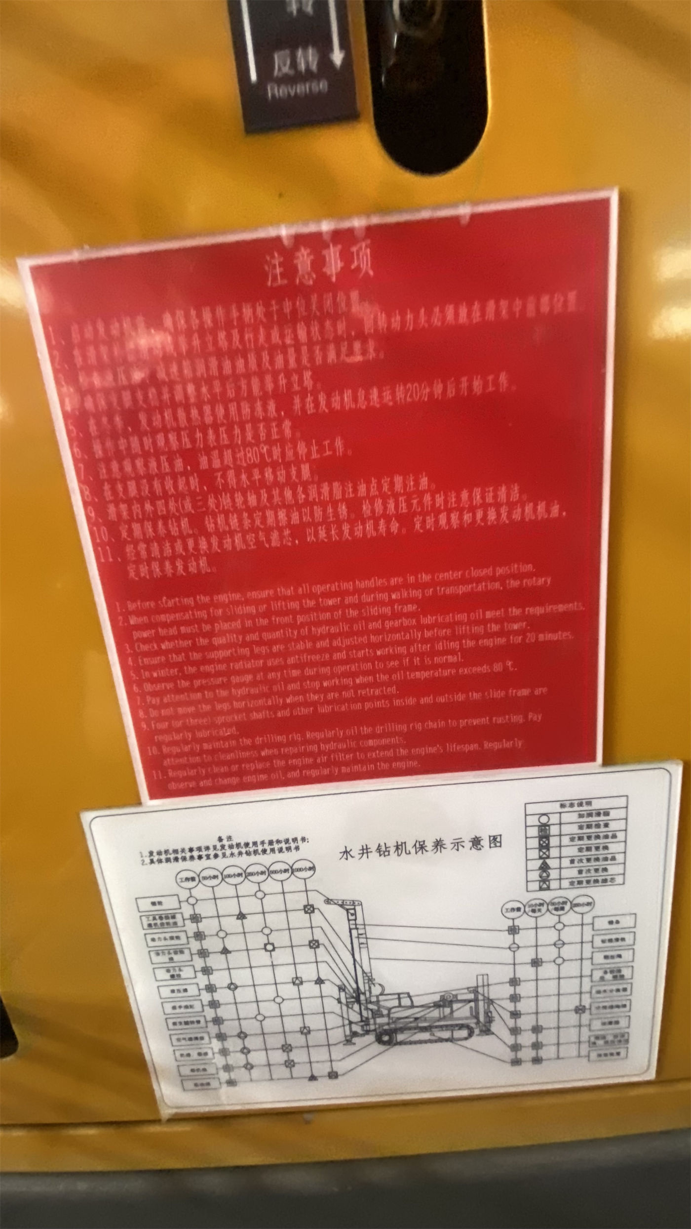
Second layer: drill string handling capacity corresponds to actual downhole loads
The deeper the borehole, the greater the drill pipe's own weight and wall friction, and the greater the lifting force required for tripping and pipe handling. WR260's specifications list a lifting force of 15 T, rotary torque of 4000–5300 N·m, rotation speed of 45–70 r/min, and 76 kW diesel power. These values correspond to conventional drill string assemblies under DTH (down-the-hole hammer) drilling conditions; the specifications mention compatibility with 76 mm or 89 mm drill pipes.
"Sufficient" here means: at the target hole depth and diameter, the lifting force can complete normal tripping, pipe handling, and DTH hammer retrieval, and the rotary torque can maintain downhole drill string rotation. The specifications also note that if pulling resistance remains abnormally high, the hole should first be cleaned and the wall and drill tools inspected, rather than directly forcing the operation with maximum lifting force. In other words, lifting force is an operating margin, not a means of resolving complex downhole incidents—this boundary should be clearly recognized during selection.
Third layer: formation and drilling process must be compatible
WR260's specifications use DTH hammer drilling as the primary method and list the supporting conditions: working air pressure reference 1.7–2.5 MPa, air consumption 17–31 m³/min. The specifications state that, with a suitable DTH hammer, bit, and air compressor, the equipment can be used in relatively intact rock formations such as limestone, sandstone, and granite. This raises a key prerequisite: DTH hammer drilling addresses the rock interval, and the air compressor's displacement and pressure must match the hole diameter, lithology, and altitude conditions; insufficient displacement causes inadequate impact and difficult cuttings removal.
In soil, clay, sand, and gravel overburden, however, the specifications clearly state that direct use of a DTH hammer may cause hole collapse and buried drills, and casing, mud, or other hole-stabilizing processes must be selected according to the formation. In weathered rock and alternating soft-hard formations, attention must be paid to wall spalling and hole shrinkage. Broken zones, fracture-developed formations, karst caves, and severely air-loss formations each have their own limitations. This shows that the third layer of "sufficient" is not determined by the equipment alone, but jointly by equipment capability and formation-process compatibility.
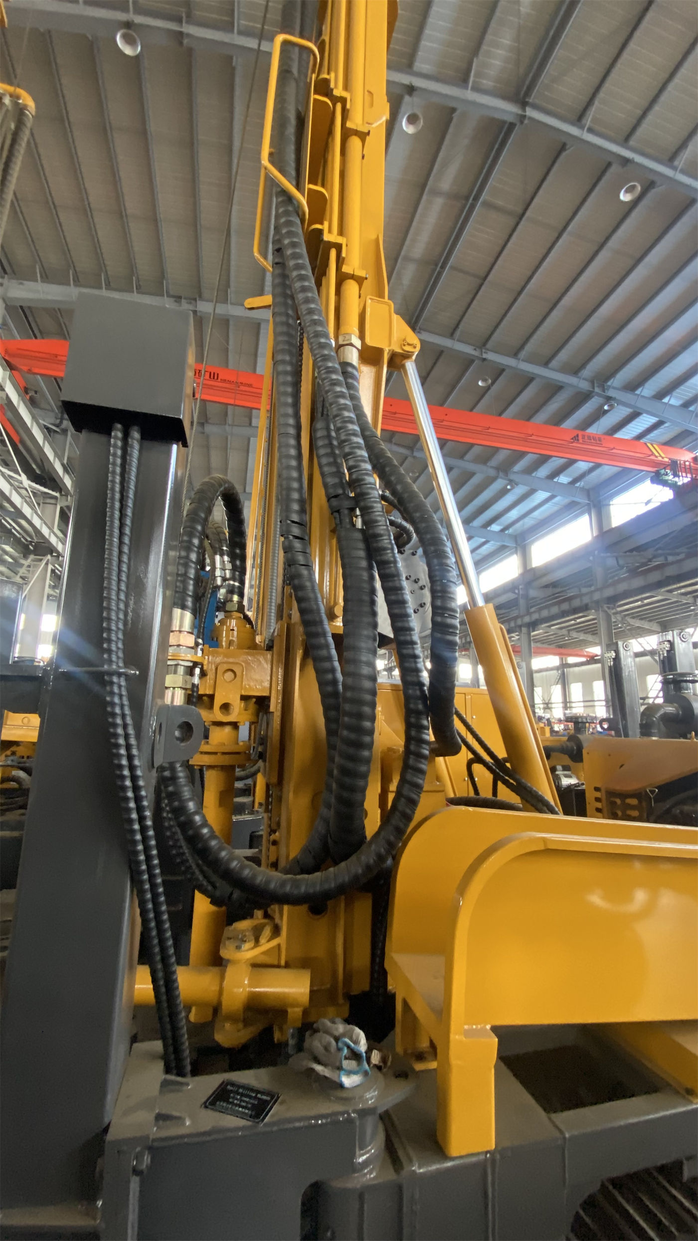
Fourth layer: site access and ground conditions must be achievable
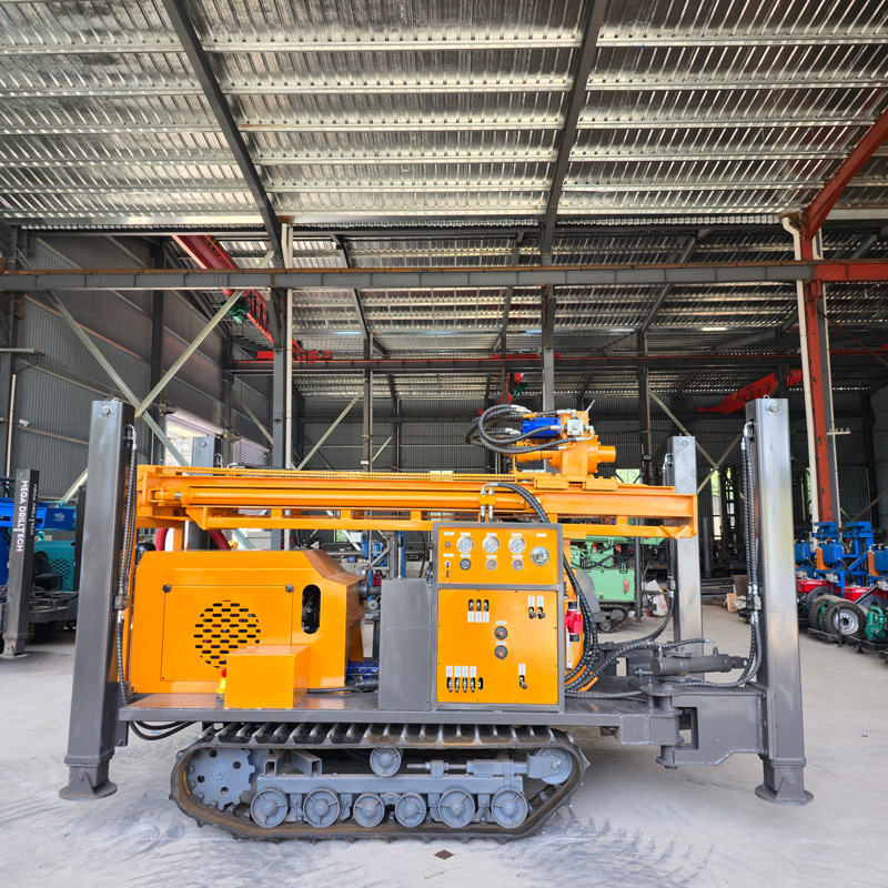
Shallow-to-medium water well projects are often scattered among village roads, fields, and plant sites. WR260 uses a steel crawler chassis with a travel speed of about 2.5 km/h, a reference maximum gradeability of 30°, an overall weight of 5.7 T, and dimensions of approximately 3900 × 1750 × 2250 mm. Outrigger stroke is 1.4 m, used for support and leveling on mildly uneven ground. These conditions correspond to the site transfer and ground adaptability layer: whether the equipment can reach the hole position smoothly and can be set up and kept stable on site.
The specifications also note that soft ground requires additional pads to prevent outrigger settlement causing mast tilt and hole position deviation; during transfer, the mast should be retracted and slope and ground bearing conditions assessed. This capability layer only provides structure and dimensions in the specifications; whether a specific site meets requirements still needs confirmation based on on-site road width, slope, ground bearing, and hole layout.
Single feed length and auxiliary configuration: affecting process continuity
WR260's single feed length is 3.3 m and can match 1.5 m, 2 m, and 3 m drill pipes. This item does not directly determine "whether it can drill," but affects the number of pipe connections and the frequency of power head return—a condition at the construction rhythm level. The specifications also list fast lifting at 24 m/min and fast feed at 40 m/min, and clarify that these speeds are for drill pipe operations and non-drilling stages, not actual penetration rates in formation; reference drilling efficiency is 10–35 m/h, with on-site results varying with rock conditions.
The auxiliary winch lifting force of 1.5 T can be used to move DTH hammers, drill pipes, and casing tools, reducing manual handling effort. The optional electric motor power scheme corresponds to fixed sites with stable power supply; final motor power, voltage, and control method should be based on the formal configuration.
One item in the specifications requiring separate confirmation
WR260's specifications include an item of 2.73 m labeled "Width of loading," which is inconsistent with the overall dimension width of 1750 mm. This article retains the original label from the specifications and does not interpret it as actual transport width. When making judgments about loading and road passage, the meaning of this item should be confirmed with formal production technical documentation and cannot be applied directly.
Restoring "sufficient" to a checklist
| Judgment item | WR260 specification correspondence | Still to be confirmed |
|---|---|---|
| Target well depth | Maximum drilling depth 260 m | Aquifer depth, completed well depth |
| Completed well diameter | Borehole diameter 140–305 mm | Well casing and submersible pump configuration |
| Drill string handling | Lifting force 15 T, torque 4000–5300 N·m | Drill string assembly, downhole friction |
| Drilling process | DTH hammer, air pressure 1.7–2.5 MPa, air consumption 17–31 m³/min | Air compressor matching, formation combination |
| Overburden and broken zones | Specifications note need for casing, mud, and other hole-stabilizing processes | Specific wall protection plan |
| Site access and ground | Steel crawler, 5.7 T, dimensions approx. 3900×1750×2250 mm | Road width, slope, ground bearing |
This table shows that WR260's published specifications can support preliminary judgments for shallow-to-medium water well projects in terms of drilling depth, hole diameter, drill string handling, and DTH hammer process, but each item still has on-site conditions to be fulfilled. Overburden thickness, aquifer water yield, actual air compressor configuration, and site access conditions are not concluded in the specifications and require item-by-item verification at the project level.
If all four main conditions above fall within the specification coverage, this 260-meter-class crawler water well drilling rig can enter selection comparison; if any one is clearly exceeded—for example, the target well depth approaches the upper limit while a larger diameter is selected, the overburden is very thick and lacks hole-stabilizing processes, or site access conditions are restricted—that condition should be resolved first before judging whether the equipment is suitable, rather than substituting the drilling depth figure for the entire conclusion.