












In a township water supply well or irrigation well project, well sites are often not concentrated: some are beside village roads, some at the end of field ridges, and some on open ground next to the village committee. The equipment must move to a new location after each well is completed, resulting in many relocations even though individual distances may not be long. What actually slows the pace is usually not the drilling itself, but rather "can the equipment get through this stretch of road, can it set up at this location, and what needs to be re-secured when changing boreholes." This article addresses this sequencing question, using public information on the WR750S to explain which conditions can be checked in advance and which must be verified on site.
First Distinguish Two Types of Movement: Relocation Between Village Roads and Positioning Within a Borehole Site
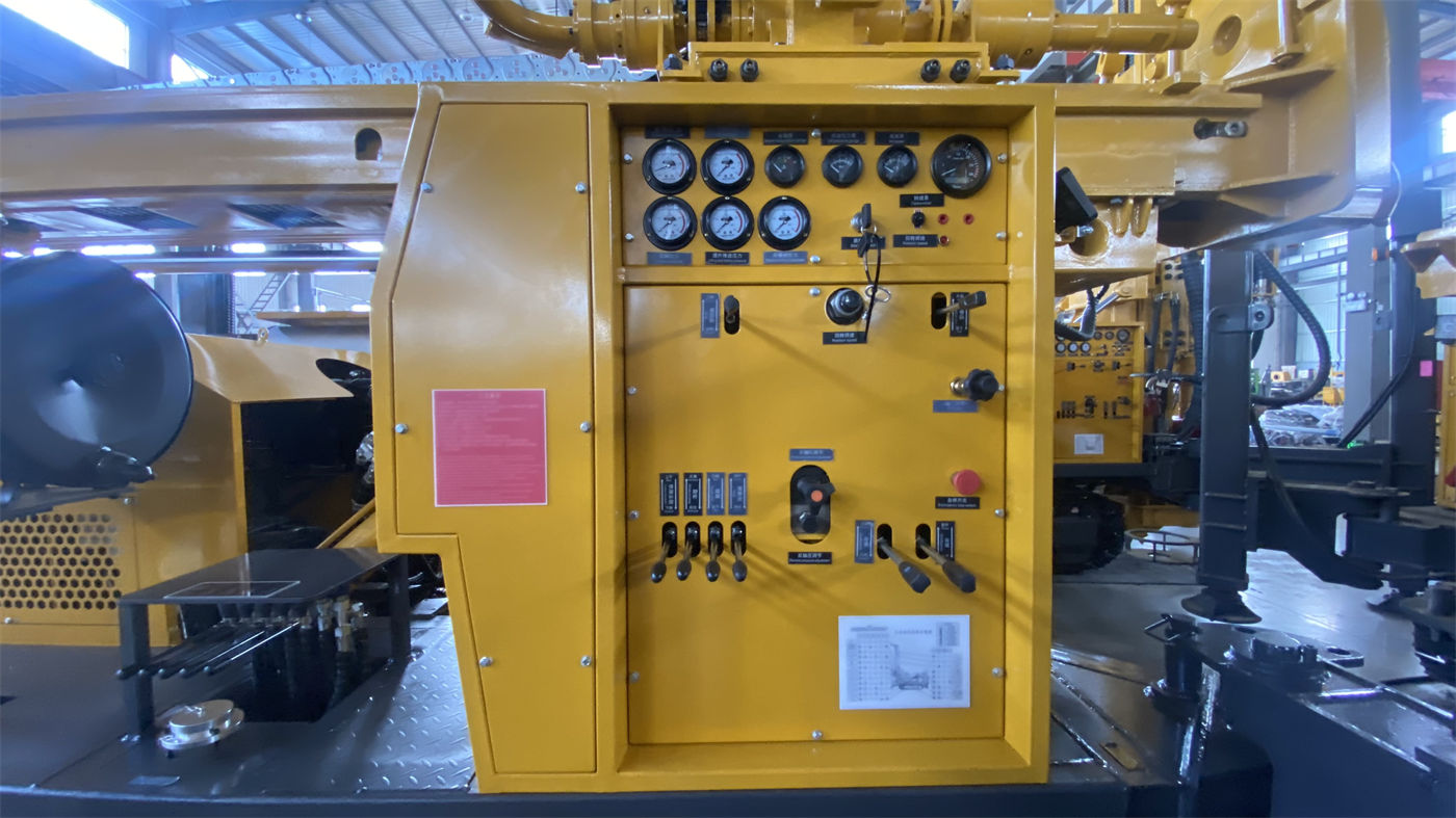
For borehole operations along village roads, movement can be divided into two stages. The first stage is moving the equipment from one borehole site to another, traveling on village roads, field roads, or gravel ground; the second stage is adjusting position within a range of a few meters to tens of meters after reaching the vicinity of the borehole site, so that the drilling tools align with the wellhead. Both stages use the crawler undercarriage, but the risk points differ: the former involves road width, turning radius, road surface bearing capacity, and height and width limits, while the latter involves site levelness, outrigger deployment space, and personnel positioning.
The WR750S materials give a crawler travel speed of approximately 3 km/h, a maximum climbing angle reference of 21°, an overall weight of approximately 14 T, and overall dimensions of approximately 6.64 × 2.25 × 2.67 m. These figures indicate that it is crawler equipment requiring careful route planning, not a light machine that can move freely between village roads. When sequencing, "road" should be placed before "borehole": first confirm whether there is a feasible route from the current borehole site to the next, then discuss how to position the equipment once it arrives.
Group Borehole Sites by Access Conditions, Not by Construction Sequence
With multiple borehole sites along village roads, if the sequence is arranged only by geological design or villagers' needs, the equipment may easily end up trapped on a narrow path it can enter but cannot leave. A more reliable approach is to first group borehole sites by access conditions:
- Borehole sites adjacent to paved village roads with space for passing and turning around;
- Borehole sites requiring travel over a stretch of dirt road or field ridge that may become soft after rain;
- Borehole sites in narrow village lanes with overhead lines or tree branches obstructing above;
- Borehole sites lacking surrounding space for pipe stacking, material placement, and personnel activity.
After grouping, the sequence is arranged to place borehole sites with similar access conditions within the same construction phase, reducing repeated switching of equipment between "easy" and "difficult" routes. This is only an organizational approach and does not represent the actual arrangement of any specific project; the actual sequence must still be determined by on-site survey and road conditions.
Items to Secure and Detach Before Relocation
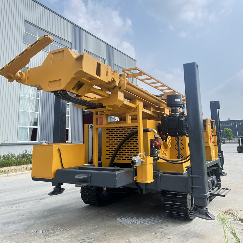
The WR750S uses a telescopic mast structure. The materials state that in transport status the mast can improve the overall transport profile and reduce the difficulty of relocation between work sites; the telescopic mast must be in a reliably locked state. In working status, it supports direct operation with 6 m drill pipes and 6 m casing. This means that before finishing one well and moving to the next borehole site, at least several items must be checked together with road conditions:
- Whether the mast has returned to transport status and is locked;
- Whether the 6 m drill pipes and casing are separately secured as required by the materials, rather than left in the working position;
- Whether drilling tools, down-the-hole hammers, casing tools, etc. are stowed in accordance with the auxiliary winch rated load and lifting safety requirements;
- Whether the overall transport profile is compatible with width limits, height limits, and turning radius along the route.
The materials mention an auxiliary winch lifting force of 2.5 T, which can be used for handling down-the-hole hammers, drill pipes, casing tools, and on-site accessories. When relocating between borehole sites along village roads, this winch is more for organizing drilling tools within the borehole site and cannot replace road transport arrangements. Separately verifying "the equipment can travel" and "the drilling tools can travel with it" is a step easily overlooked in sequencing.
After Reaching the Borehole Site, Check Outriggers and Ground First, Then Align the Borehole
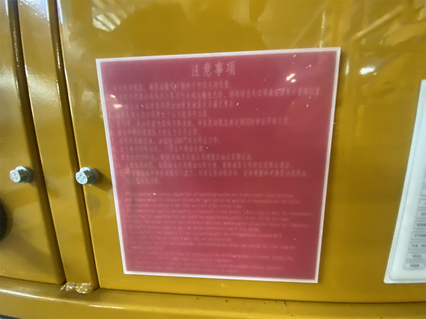
Open ground beside village roads commonly presents two situations: one where the area is sufficient but the ground is backfill or soft soil, and another where the area is barely sufficient but one side borders a ditch or a house. The WR750S materials give a hydraulic outrigger stroke of 1.6 m, which can be used for equipment leveling and stabilization; they also note that sufficient pad area should be used on soft ground. Deep-hole construction takes a long time, and the mast bears drilling string and rotary loads over an extended period, so equipment levelness and outrigger settlement control are important.
Therefore, when sequencing borehole sites, in addition to "can the road reach it," each borehole site should be annotated with "which way the outriggers extend, whether pads can fit, and where mud or circulating water drains." If these conditions are not met, the equipment may not be able to start drilling smoothly even after arrival. The materials do not provide bearing capacity values for specific sites beside village roads; such judgments can only be confirmed by on-site survey and the project party.
Support Vehicles and Material Transfer Must Be Sequenced Together with Equipment
The WR750S has an overall weight of approximately 14 T. The materials recommend confirming flatbed truck load capacity, road width and height limits, and equipment securing points for cross-project transport. For short-distance relocation between borehole sites along village roads, a flatbed truck may not be used every time, but whenever long distances or road sections where crawler travel is not permitted are involved, flatbed trucks, air compressors, mud pumps, water pipes, casing, and other supporting transport must be included in the sequence.
The materials mention optional mud pumps, centrifugal pumps, generators, and foam pumps. Deep hard-rock boreholes rely more on high-displacement air compressors and down-the-hole hammers, while projects with more loose layers rely more on mud systems. Different borehole sites may have different formation combinations, and whether supporting equipment needs to be changed and where it stops during changes will affect the relocation sequence. Listing these supporting conditions by borehole site is closer to actual construction organization than simply arranging "which well to drill first."
Conditions That Make the WR750S Worth Considering in Such Scenarios
Putting the above constraints back into the equipment materials, the WR750S's match with scattered borehole sites along village roads lies mainly in the following aspects, but each has its boundaries:
| On-site Issue | Corresponding Feature in Materials | Conditions Still to Confirm |
|---|---|---|
| Self-propelled movement needed between borehole sites | Crawler undercarriage, travel speed approximately 3 km/h, maximum climbing angle reference 21° | Village road width, turning radius, road surface bearing capacity, overhead line clearance |
| Overall profile must be retracted during relocation | Telescopic mast, transport status can improve transport profile, must be reliably locked | Lock status check, width and height limits along the route |
| Single well is relatively deep with many pipe connections | Supports direct operation with 6 m drill pipes and 6 m casing, maximum drilling depth 750 m | Target well depth, borehole diameter, whether the formation truly requires this level of capability |
| Borehole site is fragmented and requires leveling | Hydraulic outrigger stroke 1.6 m | Outrigger deployment space, soft soil pads, drainage destination |
| Drilling tools and accessories must move with the borehole | Auxiliary winch lifting force 2.5 T | Rated load, lifting safety requirements, transfer vehicles |
| Overall equipment transport | Overall weight approximately 14 T, overall dimensions approximately 6.64 × 2.25 × 2.67 m | Flatbed truck load capacity, road conditions, securing points |
These correspondences indicate that if the project truly involves deep water wells, relatively deep single boreholes, and the need for self-propelled movement between multiple borehole sites along village roads, the WR750S's crawler undercarriage and telescopic mast are directions worth including in comparison. However, the materials do not provide village road passability, specific site bearing capacity, or relocation time, so it cannot be inferred from them that it is necessarily suitable for every borehole site along village roads.
Applicable Boundaries and Items to Confirm Before Commencement
First clarify the inferences that do not apply: the 750 m drilling depth is the equipment's capability limit, not the target depth of every borehole site along village roads; a crawler travel speed of approximately 3 km/h does not mean it can relocate freely between village roads; and an improved transport profile from the telescopic mast does not mean it can pass through all village roads. The following items are not covered by the materials and must be confirmed one by one before arranging the sequence:
- The actual route from each borehole site to the main road, road surface structure, width, slope, and turning radius;
- Height and width obstacles in the village such as overhead lines, tree branches, and gatehouses;
- Outrigger deployment area around the borehole site, soft soil conditions, and pad sources;
- Mud pit or circulating water discharge locations, and the village's requirements for drainage;
- Transfer methods for supporting equipment such as air compressors, mud pumps, and casing;
- Whether flatbed trucks are needed, and whether flatbed trucks can enter village roads;
- Target well depth, borehole diameter, and formation combination for each borehole site, to determine whether 750 m-class capability is needed for all.
Scattered borehole sites alone do not constitute a selection conclusion. A more practical approach is to first compile routes, sites, and supporting conditions into a checklist, then use the equipment materials to verify which borehole sites can be entered smoothly and which require adjusting well locations or changing relocation methods. The WR750S materials can answer capability items on the equipment side, but constraints on the village road side must still be verified by on-site survey and the project party.