












For two water supply wells with similar planned depths, inquiries often come down to two crawler water well drilling rigs of different classes: one rig's drilling depth range just covers the requirement, while the other's is a step higher. The price difference is there, but the judgment cannot rest solely on 'whether the extra drilling depth is usable.' What really needs comparison is where the margin lies—whether it is margin in downhole load, margin in hole diameter and process, or merely margin in the drilling depth number. Only by looking at these separately can the capacity differences between the two classes of equipment be compared.
First Fix the Three Operating Conditions, Then Discuss Margin
Before comparison, the project's operating conditions must be clearly defined; otherwise, there is no basis for comparing margins. For crawler water well drilling rigs, at least three items need to be determined first:
- The expected depth of the target aquifer and the maximum planned construction well depth for the project;
- The final hole diameter required for the completed well structure and the dimensions of well casing and screen pipes;
- The formation combination from overburden to bedrock and the drilling method planned for each hole section.
Once these three are determined, examining the drilling depth, hole diameter, lifting force, rotary torque, and air supply requirements in the equipment materials allows one to judge which are 'just covering,' which 'leave margin,' and which are not covered by the materials and require confirmation from the manufacturer or on site. The drilling depth number is only one item; it answers 'how deep can it go at most,' not 'can it still run trips, remove cuttings, and complete the well properly at that depth.'
Margin 1: Load of the Drill String in the Hole
With similar well depths, drill string loads can still differ due to different hole diameters and drill pipe specifications. The deeper the hole, the more pronounced the superposition of drill pipe weight, thread load, borehole wall friction, and local diameter reduction; during tripping out, these resistances and the weight of the drilling tools must be lifted together. The magnitude of the lifting force directly determines whether tripping is smooth and whether the DTH hammer and partial casing can be handled normally.
Taking the public materials of WR600S as an example, its lifting force is 35 T, feed force 6 T, and recommended drill pipe diameter 89 / 102 mm, length 6 m. For 600-meter-class deep holes, the drill pipe weight and friction will significantly increase the tripping load; the 35 T lifting force corresponds to the space required for handling such deep-hole drill strings, not an inevitable value at a fixed well depth. For a specific project, it must also be calculated in conjunction with the final hole diameter, drill pipe material and connection strength, and whether casing is run.
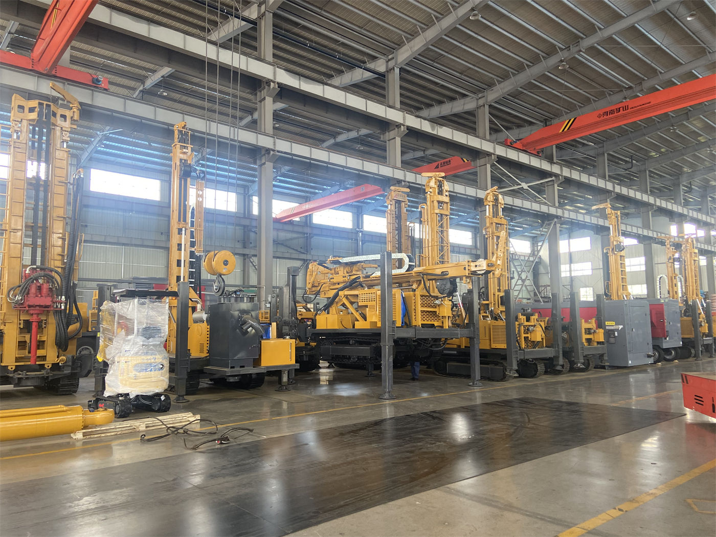
When comparing two classes of equipment, one should not only look at whose lifting force number is larger but also whether it matches the drill pipe specifications and auxiliary winch. The auxiliary winch lifting force of WR600S is 2.5 T, which can be used for on-site handling of DTH hammers, drill pipes, and casing tools; such auxiliary capacity also affects process continuity when changing drilling tools frequently in deep holes.
Margin 2: Switching Between Rotary Torque and Rotation Speed Conditions
The margin in the rotary section is not 'the higher the torque, the better,' but whether the equipment has operating conditions corresponding to different downhole resistances. Hard rock, large hole diameters, and high-friction hole sections require low speed and high torque; when resistance is lower or drilling tool load is lighter, increasing rotation speed can reduce auxiliary time.
The rotary system of WR600S features dual-condition torque of 12000 / 6000 N·m, corresponding to maximum rotation speeds of 90 / 180 r/min. The materials describe this configuration in the context of deep holes, hard rock, large hole diameters, and alternating soft-hard formations: when downhole resistance changes, the combination of torque and rotation speed can be switched to maintain rotation. When comparing two classes of equipment, it should be clarified: which hole sections each rig's torque stages cover, by what means the switching is achieved, and what requirements switching imposes on cuttings removal and feed. The materials only give the correspondence between torque and rotation speed, not the applicable limits of each stage in specific formations; this part needs to be judged in conjunction with the bit, DTH hammer, and cuttings return conditions.
Margin 3: Mast, Outriggers, and Drilling Attitude
With similar well depths but different mast forms, the operating rhythm will differ. WR600S adopts a telescopic mast, allowing direct use of 6 m drill pipes during operation, reducing the number of pipe connections in deep well construction; during transport, the telescopic structure improves the overall outline. For 600-meter-class drilling with many pipe connections, the effect of long drill pipes in reducing auxiliary time is more pronounced, which is why mast form becomes a comparison item.
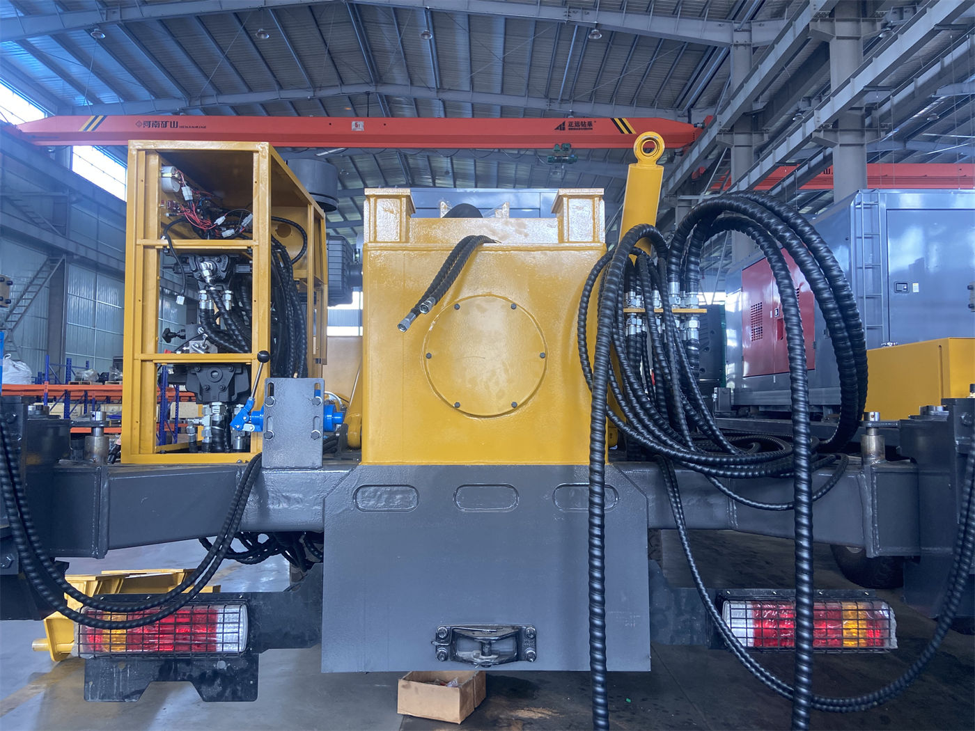
The greater the hole depth, the more directly overall machine stability affects mast stress and hole deviation control. The hydraulic outrigger stroke of WR600S is 1.6 m, used for equipment leveling and stable support; the materials also note that pads should be used on soft ground to ensure uniform outrigger stress and avoid settlement after prolonged operation. When comparing two classes of equipment, outrigger stroke and support method should be included in the checklist, especially when hole locations are on farmland, backfill, or gravel ground.
Margin 4: Supporting Air Supply and Circulation Process
If the project plans to use DTH hammer drilling, air supply is not just a matter of the equipment itself but a condition for whether the overall machine solution is viable. The WR600S materials state that the working air pressure for DTH drilling is 1.2–3.5 MPa, with air consumption of 16–55 m³/min, and note that when hole depth increases, hole diameter enlarges, rock hardness increases, or altitude rises, the actual required displacement may increase; the air compressor must be matched separately for the project.
This point is easily overlooked when comparing two classes of equipment: a higher drilling depth class does not mean the supporting air compressor can be copied directly. If the upper overburden requires mud rotary drilling and the lower bedrock switches to DTH hammer, mud pumps, casing, foam, and other wall protection measures must also be included in the plan. The WR600S materials indicate that upper soil layers, clay, sand layers, and gravel layers can use mud rotary drilling, and after entering more stable rock, switch to DTH; such process continuity corresponds to a supporting equipment list, not just the main machine's capacity.
Margin 5: Site Entry and Relocation Conditions
No matter how large the capacity margin, it cannot be realized if the equipment cannot reach the hole location. The WR600S has an overall weight of approximately 12.5 T, dimensions of approximately 6.73 × 2.1 × 2.63 m, walking speed of approximately 3 km/h, and maximum climbing angle reference of 21°. The materials note that during transport, flatbed trucks should be arranged according to vehicle load, road width, and height limits, and the telescopic mast locking and equipment securing should be checked; after arriving at the site, space for mast unfolding must be reserved.
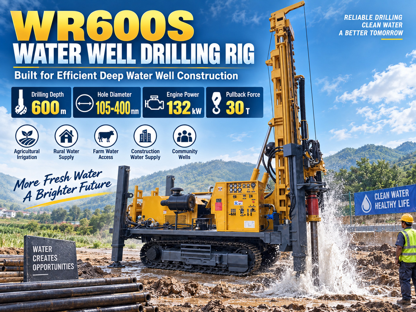
If the two classes of equipment differ in tonnage and overall dimensions, the judgment of passability on village roads, field ridges, and mining area roads will also differ. During comparison, road width, turning radius, ground bearing capacity, and hole location unfolding space should be checked as preconditions, rather than dealt with after the equipment arrives.
Put the Comparison Items Back into the Same Table
| Comparison Item | Question to Answer | Corresponding Content in WR600S Materials |
|---|---|---|
| Drilling depth and hole diameter | Whether both the target well depth and final hole diameter fall within the covered range | Maximum drilling depth 600 m; hole diameter 105–400 mm |
| Lifting force | Whether there is margin for deep-hole tripping, DTH hammer recovery, and casing operations | Lifting force 35 T; feed force 6 T |
| Rotary torque | Whether hard rock, large hole diameter, and low-resistance hole sections can be handled in stages | 12000 / 6000 N·m; maximum rotation speed 90 / 180 r/min |
| Drill pipe and mast | Number of pipe connections, transport outline, and mast unfolding space | 6 m drill pipe; 89 / 102 mm; telescopic mast |
| Air supply support | Whether the DTH hammer process has matching air compressor displacement and pressure | 1.2–3.5 MPa; 16–55 m³/min |
| Site entry conditions | Whether roads, bearing capacity, and site can meet overall machine transport and unfolding | Approx. 12.5 T; approx. 6.73 × 2.1 × 2.63 m; walking approx. 3 km/h; climbing reference 21° |
The table only puts together the content that can be matched in the materials; it cannot replace the project's conclusion on 'which rig to choose.' Whether the capacity margin of two classes of equipment is worthwhile depends on the project's future well depth distribution, hole diameter changes, and formation uncertainty: if planned well depths are concentrated in one range, hole diameters are fixed, and formation data are clear, the actual value of drilling depth margin is limited; if the same rig must handle different well depths and different hole diameters across multiple hole locations, the margin lies more in the mast, lifting force, and torque stages.
Items Still Requiring Confirmation Beyond the Materials
- The actual depth and water yield of the target aquifer should be based on hydrogeological data or preliminary exploration; the maximum drilling depth should not be taken as the construction target;
- The casing, screen pipes, and pump type corresponding to the final hole diameter need to be determined by the well completion design;
- The specifications and sources of supporting equipment such as air compressors and mud pumps need to be matched separately for the project;
- The actual passability and unfolding conditions of the two classes of equipment at the same site should be verified on site before commencement, including road width limits, height limits, and ground bearing capacity;
- The materials do not provide the specific formation applicability limits of the two classes of equipment under each torque stage; comparison should not infer that 'one class is necessarily more suitable' based on this.
After breaking down and comparing the above items, 'similar well depth' is no longer the starting point of comparison but one dimension of it. Whether to pay for the margin depends on whether it can be converted into actually usable operating conditions in terms of lifting force, torque stages, mast form, and supporting processes.