












Before equipment moves in for a deep well water supply well, what really determines whether things go smoothly later is often not the drilling rig model, but whether several documents and site conditions have been confirmed: roughly what depth the aquifer is at, what borehole diameter is required for well completion, how to stabilize the upper loose layer, whether the air compressor can keep up, which road the equipment will enter from, and whether the site can be laid out. Fixing these things after work starts usually costs far more than confirming them once on paper.
Below, following the two lines of "documentation" and "site conditions," the items worth checking one by one before construction are listed, and the public information of the WR500SE is used as a reference to explain which conditions are directly related to equipment capability and which are project-level matters that must be separately confirmed. This article does not involve specific project cases, and the order listed is for reference only.
First group of documents: target well depth and aquifer information
The depth of a deep well water supply well is not determined by first setting a number and then finding equipment; it is jointly determined by the aquifer location, water volume demand, and local hydrological data. Before construction, at least two types of information should be obtained: first, regional hydrological data or completion records of nearby wells, used to determine the approximate depth range of the main aquifer; second, the designed well depth and expected water yield of this well.
The role of these two types of information is to provide a basis for judging equipment capability, not to make every well drill to the equipment limit. The WR500SE documentation specifies a maximum drilling depth of 500 m and a borehole diameter of 140–350 mm, and it can be used for medium-to-deep groundwater projects such as rural deep wells, farmland irrigation wells, industrial water wells, and mining area water supply. The documentation also states that a 500-meter-class drilling depth does not mean every project must drill to the limit; the actual construction depth should be determined based on the aquifer location and local hydrological data. Therefore, the designed well depth and aquifer depth data are items that must be confirmed first before construction, and the equipment drilling depth is only a reference for the coverage range.
Second group of documents: well structure and completion borehole diameter
The completion borehole diameter, well pipe specifications, screen pipe position, and water-stop section arrangement determine how large the borehole diameter must be opened, and also affect the selection of drilling tools and casing. Before construction, the following should be clarified: final borehole diameter, whether staged reaming is required, well pipe outer diameter and running depth, and the depth interval of the screen pipe section.
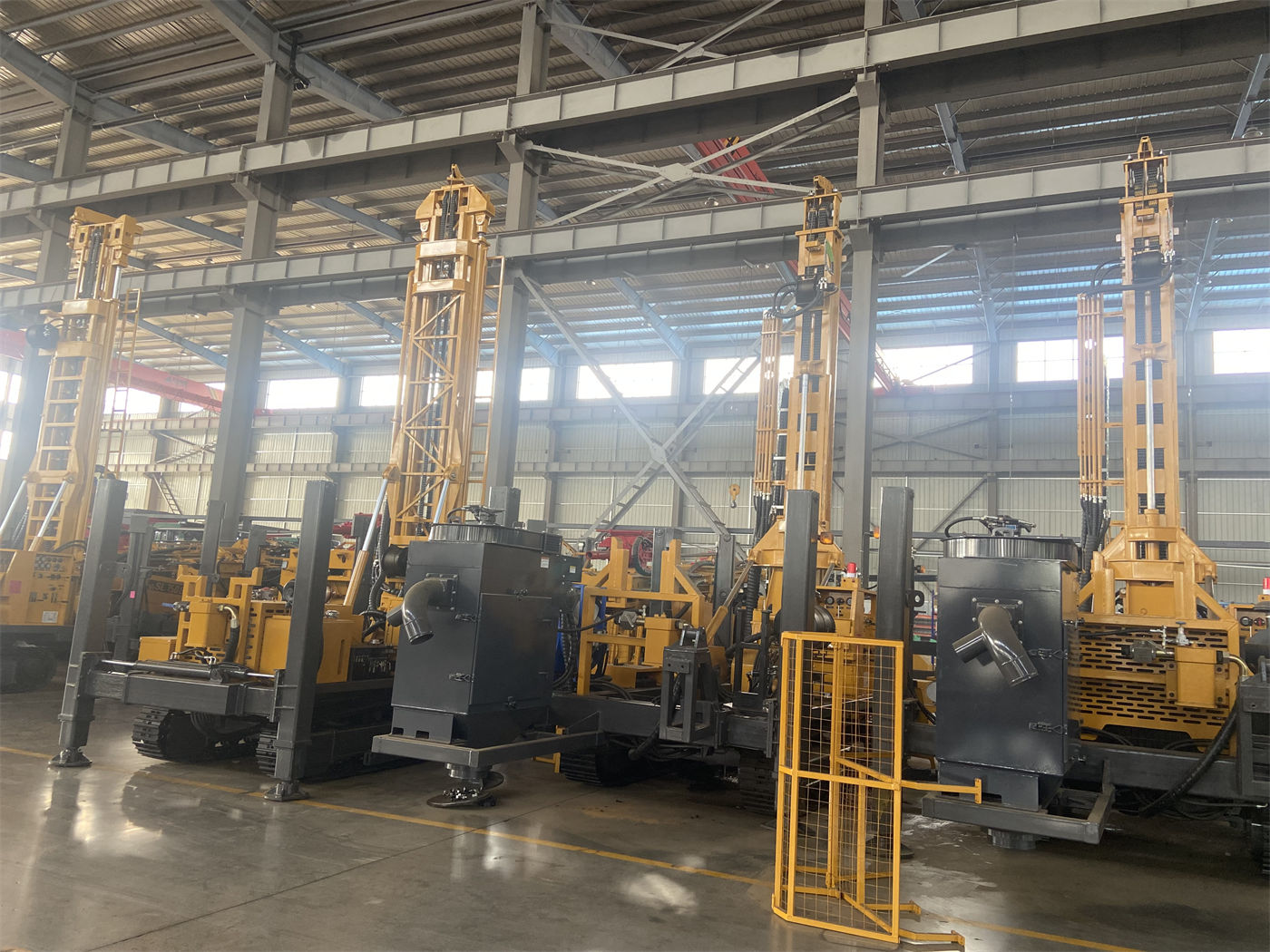
The WR500SE has a borehole diameter range of 140–350 mm, supports three drill pipe outer diameters of 102 / 108 / 114 mm, and offers lengths of 1.5 / 2 / 3 / 6 m. Looking at these parameters together with the well structure allows a preliminary judgment of whether there is matching space for the drilling tool combination; however, which drill pipe outer diameter and length should be selected for a specific well still needs to be determined based on borehole diameter, hole depth, formation, and site space. The documentation itself does not provide a single answer.
Third group of documents: formation combination and drilling process
A common situation in deep well water supply wells is an upper soil layer, sand layer, or gravel layer, with rock formation below. The two types of hole sections have different process requirements. Before construction, a formation column description or drilling records of nearby wells should be prepared to determine whether casing is needed, whether mud stabilization is needed, and whether the lower rock formation will use down-the-hole hammer drilling.
- Upper loose overburden: The documentation states that casing, mud, or other stabilization methods can be used according to the project, first establishing a stable wellhead and upper hole section before entering the lower rock formation. When the loose layer is thick, the mud system should be considered in advance during the equipment matching stage.
- Weathered layer and alternating soft-hard formations: Hole wall collapse and diameter shrinkage are likely, and parameters need to be adjusted during construction according to changes in rotary torque, advancement resistance, and cuttings return; when necessary, casing should be used for unstable upper hole sections.
- Intact hard rock: With a suitable down-the-hole hammer and air compressor, the WR500SE can be used in relatively intact formations such as granite, basalt, limestone, and sandstone. Hard rock construction should maintain down-the-hole hammer lubrication and stable cuttings discharge.
- Fractures, broken zones, and air-loss formations: These may cause block falling, air loss, stuck drilling, and abnormal cuttings return. The WR500SE is equipped with an auxiliary foam pump function, which can improve cuttings discharge in some dry, fractured, and air-loss formations; when air loss is severe, it should be handled comprehensively with foam, casing, and air compressor displacement.
The above are the formation correspondences listed in the documentation and serve as references for process direction. Whether a specific well needs casing, mud, or foam must be judged by the project based on actual formation and hydrological conditions.
Fourth group of conditions: air compressor and air supply support
If the lower rock formation uses DTH down-the-hole drilling, the air compressor is not optional but supporting equipment that must be confirmed before construction. The WR500SE documentation gives a recommended working air pressure of 1.7–3.5 MPa and air consumption of 17–42 m³/min. The documentation also reminds that when borehole diameter increases, rock formation hardens, hole depth increases, or altitude rises, more sufficient air flow is needed, and rated pressure alone should not be the only consideration.
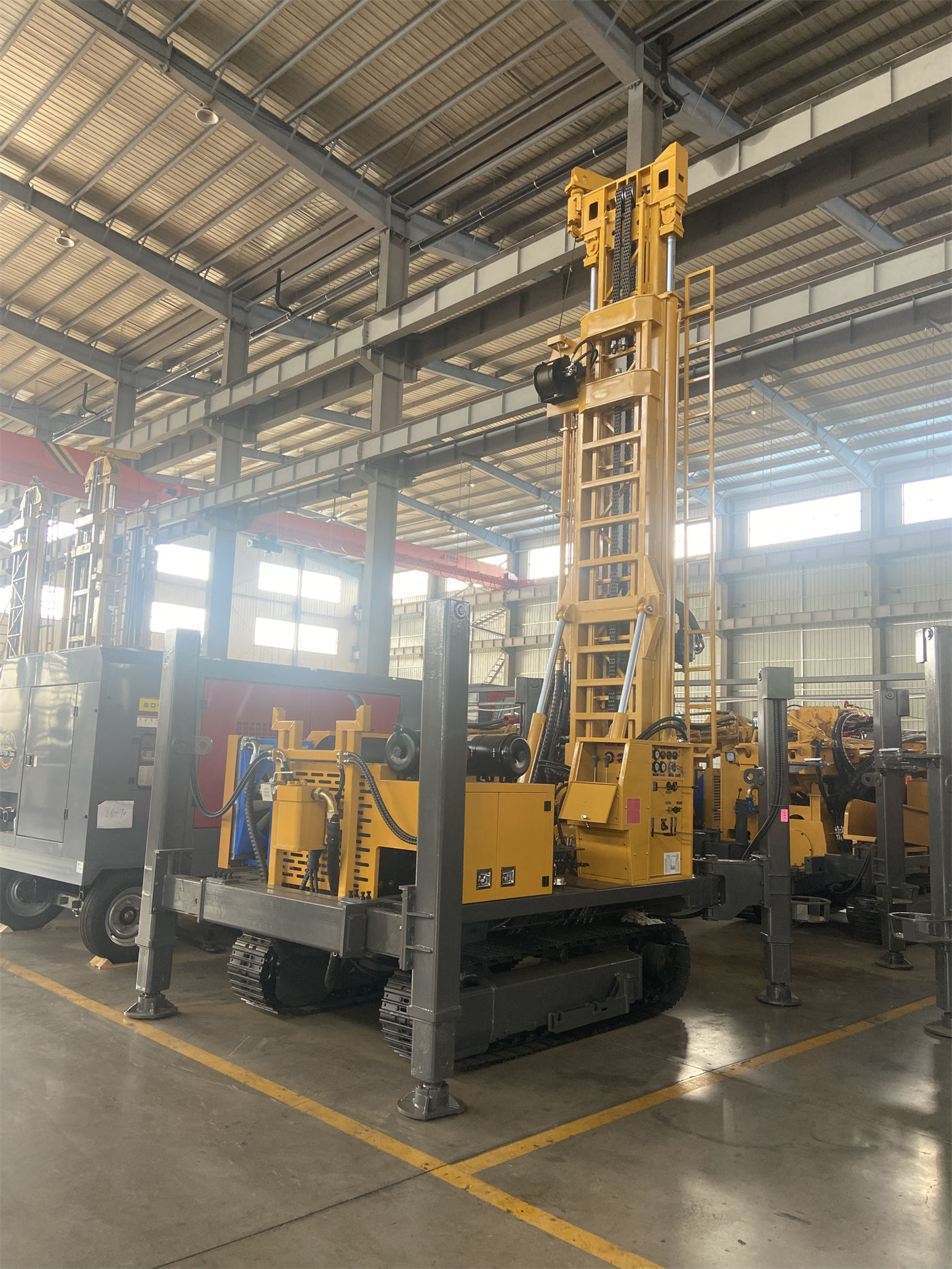
Therefore, before construction, confirm: whether the actual displacement and pressure of the proposed air compressor fall within the above range, whether the site altitude and temperature will affect actual air supply capacity, and whether the pipeline length and joints have significant pressure drop. These are supporting conditions and are not parts that the drilling rig itself can replace.
Fifth group of conditions: site, outriggers, and relocation route
Before the equipment arrives, the site and route should be inspected first. The WR500SE has an overall weight of about 9.5 T, overall dimensions of about 6150 × 2200 × 2600 mm, and adopts a 6.6 m long-stroke telescopic mast. The documentation states that due to the long-stroke configuration, vehicle length and securing method should be confirmed before transport. This must be confirmed in the pre-construction transport arrangements.
Regarding site conditions, the equipment travel speed is about 2.5 km/h, with a reference maximum gradeability of 30°. The crawler structure is suitable for rural roads, mining area gravel ground, and generally uneven sites. The documentation also notes that actual gradeability and relocation should consider the overall center of gravity, ground wetness and slipperiness, and mast transport state, and safety should not be judged only by the maximum angle. The outrigger stroke is 1.6 m, allowing support and leveling on mildly uneven sites; on soft ground, pads should be added to prevent outrigger sinking after long construction periods. These are all matters to be considered together in pre-construction site preparation.
Sixth group of conditions: matching of drill string, casing, and lifting capacity
Drill string handling and some casing operations in deep well water supply wells are directly related to the equipment's lifting capacity. The WR500SE has a lifting force of 26 T, rotary torque of 7500–10000 N·m, and rotation speed of 45–130 r/min. The documentation states that the 26 T lifting force can be used for 500-meter-class drill pipe tripping, down-the-hole hammer recovery, and some casing operations; in deep holes, once diameter shrinkage, block falling, or sediment occurs, tripping resistance increases rapidly, so lifting capacity should be treated as normal operating margin, not the only means of handling all downhole incidents.
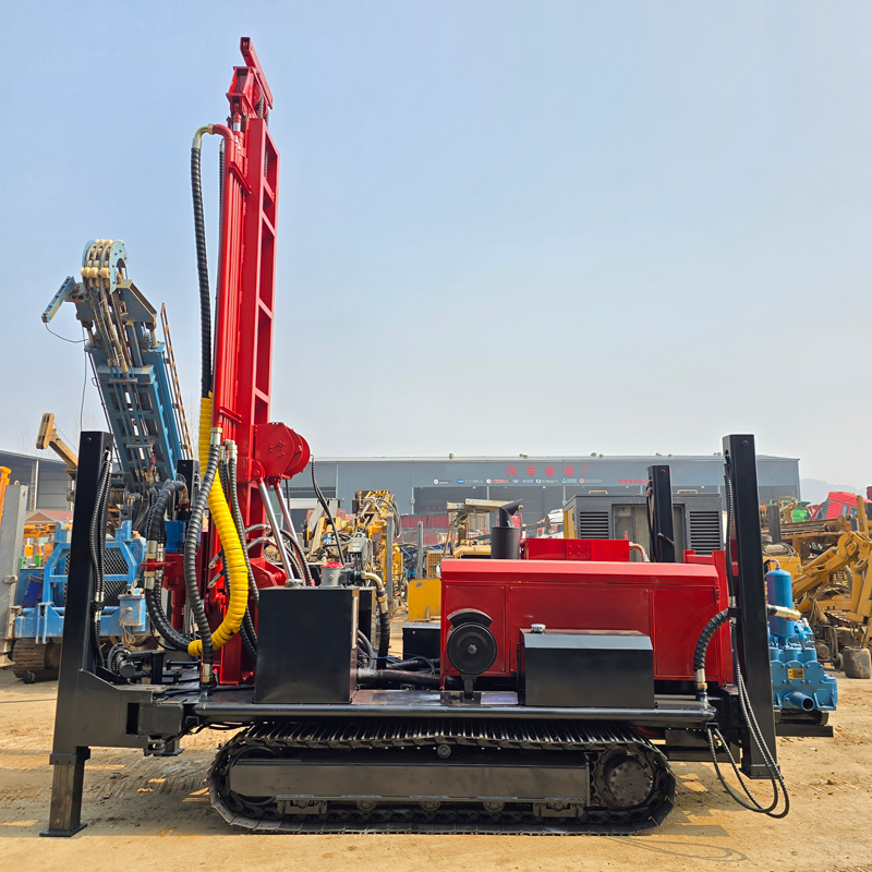
Before construction, check accordingly: the weight of the proposed drill pipe combination at the target hole depth, casing specifications and running depth, and whether auxiliary winch cooperation is needed. If the designed well depth is close to the equipment drilling depth limit, or the casing section is long, the lifting margin should be separately confirmed rather than assumed to be sufficient.
Putting the preparation items back into a checklist
| Preparation item | Content to be confirmed before construction | Corresponding point in WR500SE documentation |
|---|---|---|
| Aquifer and designed well depth | Regional hydrological data, completion records of nearby wells, designed well depth and expected water yield | Maximum drilling depth 500 m; construction depth should be determined based on aquifer location and hydrological data |
| Well structure | Final borehole diameter, well pipe outer diameter, depth of screen pipe and water-stop section | Borehole diameter 140–350 mm; drill pipe 102 / 108 / 114 mm, length 1.5 / 2 / 3 / 6 m |
| Formation and process | Formation column description, upper stabilization method, whether down-the-hole hammer drilling is used below | Documentation lists corresponding directions such as casing, mud, and auxiliary foam pump |
| Air supply support | Air compressor displacement and pressure, altitude and pipeline pressure drop | Recommended air pressure 1.7–3.5 MPa, air consumption 17–42 m³/min |
| Site and relocation | Access road, transport vehicle length, site leveling and pads | Overall machine about 9.5 T; dimensions about 6150 × 2200 × 2600 mm; outrigger stroke 1.6 m |
| Drill string and casing | Drill pipe combination weight, casing specifications and running depth | Lifting force 26 T; torque 7500–10000 N·m |
What still needs on-site confirmation
The above documentation can answer which range the equipment capability covers, but it cannot replace on-site judgment. At least the following types of matters must be separately confirmed before construction:
- The actual depth and water yield of the target aquifer; the documentation does not include hydrological data for specific projects.
- The actual thickness and stability of the upper loose layer, which determine the stabilization method and casing usage.
- The actual air supply capacity of the air compressor under the project site's altitude and temperature conditions.
- The load-bearing capacity and turning radius of the access road, as well as the securing plan for transport vehicles and the long-stroke mast.
- The load-bearing condition of soft soil layers on site, and whether additional pads or replacement fill are needed.
- If the designed well depth is close to 500 m, whether the actual load of the drill string and casing is still within the lifting margin.
Putting these documents and conditions on paper first and then looking at equipment parameters will make the judgment better grounded. The public information of the WR500SE can serve as a reference sample for this kind of check: its drilling depth, borehole diameter, lifting force, torque, air supply range, and overall dimensions each correspond to a certain group of pre-construction preparation items, but which item is the constraint and which still has margin ultimately still depends on the specific well design and site conditions.