












When water well construction crews discuss equipment efficiency, they often talk about "how far it can feed in one stroke" and "how long a single drill pipe is" separately. The former refers to the stroke of the power head or feed mechanism, while the latter refers to the length of a single drill pipe. Neither figure is difficult to understand on its own, but when it comes to the actual drilling rhythm of medium-deep water wells, they must be matched: no matter how long the stroke is, if the drill pipe is only 3 m, frequent rod connections cannot be avoided; and no matter how long the drill pipe is, if the effective stroke after the mast is deployed does not match the space needed for tripping, the connection advantage of long drill pipes cannot be realized. This article focuses on this matching relationship and, based on publicly available information on the WR400S, explains which conditions support this combination and which conditions still need to be confirmed on site.
First Distinguish the Two Operations: Feed Stroke Governs In-Hole Penetration, Drill Pipe Length Governs the Number of Connections
Feed stroke constrains how far the drilling tool can travel continuously in the axial direction in one pass in the hole, and it is related to the feed stroke, mast height, and power head position. Drill pipe length constrains how much hole depth each rod can cover and how often the drill pipe must be connected and disconnected. The former affects the continuous drilling time within a single drill pipe, while the latter affects the total number of auxiliary operations for the entire well.
If only the feed speed is increased while the drill pipe is very short, auxiliary actions such as connecting rods, disconnecting rods, and tripping will still repeatedly interrupt penetration; if only long drill pipes are used while the equipment mast, stroke, and tripping space do not match, the advantages of long drill pipes likewise cannot be realized. Therefore, when evaluating a medium-deep water well drilling rig, these two figures should be checked in the same process table rather than viewed separately.
Several Items in the WR400S Information Directly Related to This Combination
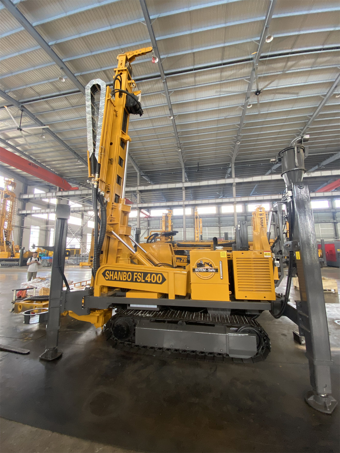
The WR400S is a 400 m-class telescopic-mast crawler water well drilling rig. The items in the information directly related to the rod-connection rhythm are as follows: it supports direct operation with 6 m drill pipe and 6 m casing, with recommended drill pipe diameters of 89 / 102 mm; maximum drilling depth 400 m, drilling diameter 105–325 mm; rotary system maximum torque 8000 / 4000 N·m, corresponding to maximum rotation speeds of 75 / 150 r/min; lifting force 22 T, axial pressure 4 T; fast lifting 29 m/min, fast feed 56 m/min; overall weight approximately 9.8 T, overall dimensions approximately 6.26 × 1.85 × 2.43 m.
These figures cannot be taken alone as efficiency conclusions. What they show is that in 300–400 m-class water wells, 6 m drill pipe can reduce the number of rod connections, and the telescopic mast can shorten the overall transport profile in the transport state while still supporting direct construction with 6 m drill pipe or 6 m casing in the working state. As for how much auxiliary time can actually be saved, this depends on the formation, hole diameter, drilling tool assembly, and site organization. The information does not provide quantitative results, nor should one be invented for it.
Why the 6 m Drill Pipe and Telescopic Mast Must Be Considered Together
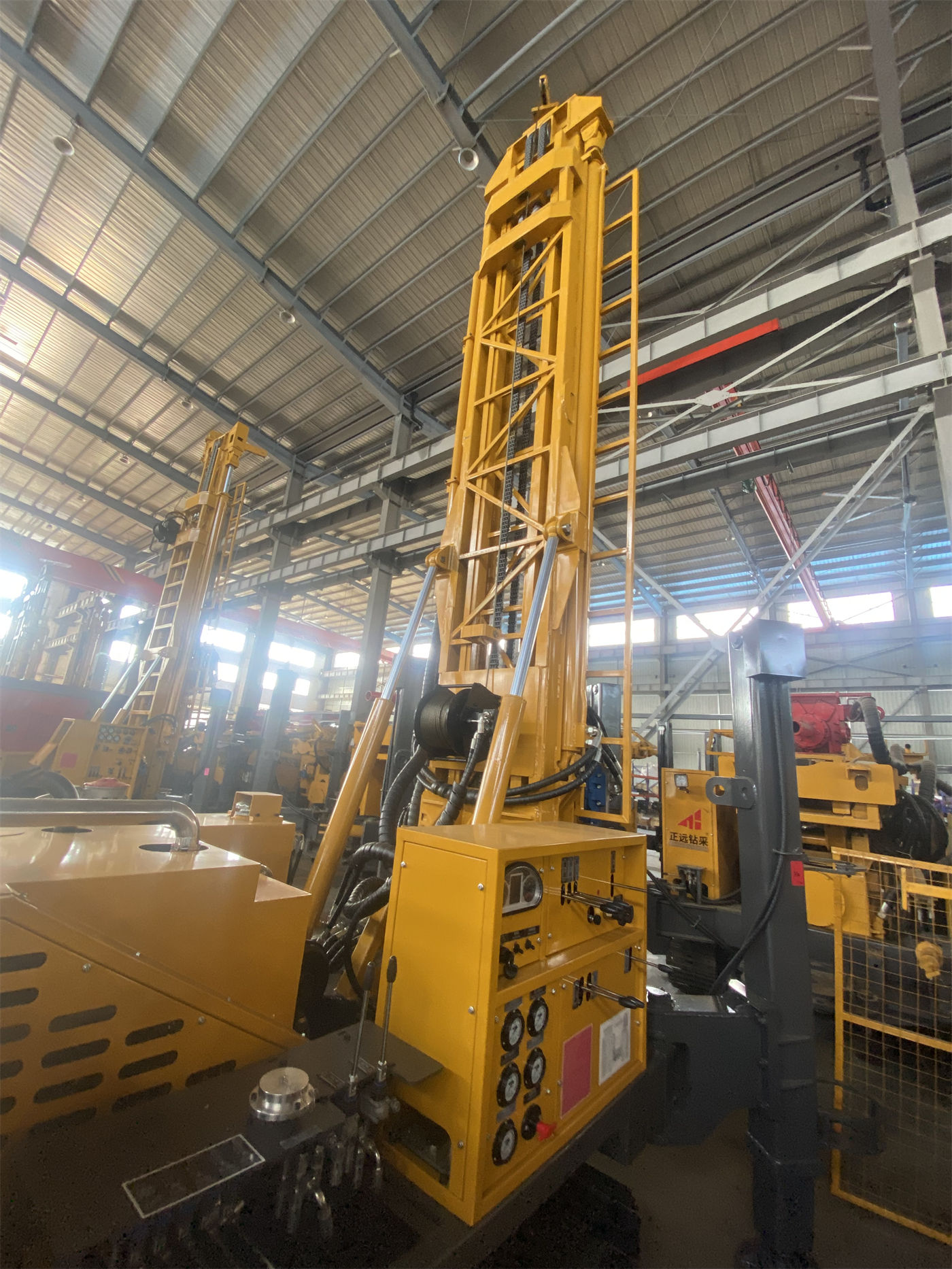
The reduction in the number of rod connections brought by long drill pipes presupposes that the mast has enough space in the working state to accommodate and trip this drill pipe. The structural value of the telescopic mast lies in handling the transport profile and the working profile separately: during relocation, the mast is shortened, reducing the difficulty of loading and road passage; after deployment at the hole position, it continues to maintain 6 m drill pipe construction capability. For crews drilling across regions, working on village and town projects, and carrying out continuous construction at multiple sites, this structure alleviates the contradiction that "long drill pipes require a tall mast, while a tall mast is unfavorable for relocation."
Conversely, if the project's hole positions are concentrated and relocations are rare, the transport convenience brought by the telescopic mast is not the main contradiction, and the focus of judgment should return to drilling depth coverage, hole diameter range, and formation processes. If the project's well depth is relatively shallow, the significance of 6 m drill pipe in reducing the number of rod connections will also diminish accordingly. Therefore, this matching relationship is conditional, and not all water well projects follow the same logic.
Put Requirements, Information, and Supporting Conditions into the Same Checklist
| Operational Requirement | Corresponding Item in the Information | Conditions Still to Be Confirmed |
|---|---|---|
| Reduce the number of rod connections in medium-deep holes | Supports direct operation with 6 m drill pipe, recommended diameters 89 / 102 mm | Drilling tool assembly, in-hole resistance, actual supplied drill pipe specifications |
| Control the difficulty of loading during relocation | Telescopic mast, transport profile can be shortened | Road width, turning radius, transport vehicles and securing methods |
| Cover the target well depth and completed well diameter | Maximum drilling depth 400 m, drilling diameter 105–325 mm | Target aquifer depth, completed well structure, well casing and pump type |
| Handle drill strings and casing in medium-deep holes | Lifting force 22 T, auxiliary winch 1.5 T | Actual drill string weight, casing weight, borehole wall friction |
| Transition between hard rock and loose layers | Supports DTH hammer and mud drilling, working air pressure 1.2–3.5 MPa | Air compressor pressure and displacement, formation air leakage, wall protection plan |
The purpose of this table is not to give the conclusion "choose it," but to check feed stroke, drill pipe length, and supporting conditions separately. If any row does not hold, the rhythm improvement brought by fewer rod connections may be offset by other links.
Supporting Conditions and Application Boundaries
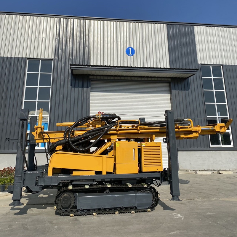
The information shows that the WR400S uses a 92 kW Yuchai engine, has a crawler travel speed of approximately 2.5 km/h, a maximum climbing angle reference of 21°, and a hydraulic outrigger stroke of 1.6 m. These conditions indicate that it is suitable for rural roads, gravel ground, and generally uneven sites, but soft ground still requires the use of mats, and ground bearing capacity and slope must be assessed before relocation. Direct operation with 6 m casing is helpful for the completed well structure, but the design of the well casing, filter pipe, and sealing section must still be determined according to aquifer conditions.
When using a DTH hammer in hard rock sections, the recommended working air pressure is 1.2–3.5 MPa and air consumption is 16–55 m³/min; the pressure and displacement of the air compressor must match simultaneously. When using mud drilling in loose layers, accessories such as mud pumps and centrifugal pumps are supporting conditions of the overall machine solution and need to be configured separately for the project. The information also notes that if abnormal resistance occurs during tripping, the hole should first be cleaned and the presence of hole shrinkage, falling blocks, or stuck drilling should be determined; the maximum lifting force should not be used directly to force handling.
Matters to Confirm with the Manufacturer or Project Party
- The applicability of 6 m drill pipe under actual drilling diameter and formation conditions, and whether the recommended drill pipe diameters of 89 / 102 mm are consistent with the planned drilling tool assembly.
- Whether the effective working space after the telescopic mast is deployed connects smoothly with the 6 m casing running procedure; the information does not provide item-by-item process descriptions.
- Whether the target well depth, completed well diameter, and local hydrogeological conditions fall within the 400 m and 105–325 mm ranges; the actual completed well depth should still be determined according to hydrological data.
- The specific specifications and supply scope of supporting accessories such as air compressors, mud pumps, generators, and foam pumps.
- The information does not provide actual penetration efficiency, rod connection time, or cost changes under different formations; these need to be measured by project or evaluated by the construction party.