












For a water well planned to a depth of around 300 meters, the question construction teams most often hear during inquiries is "is the drilling depth sufficient?" However, whether equipment can be used smoothly on a project does not depend solely on maximum drilling depth: what diameter the completed well requires, how the upper loose layers are stabilized, whether 3-meter or 6-meter drill pipes are used, whether the air compressor's air volume can keep up, and whether the equipment can be driven next to the hole location to deploy its outriggers—if any one of these conditions is blocked, the drilling depth figure alone cannot answer the question. This article uses several practical constraints of conventional water well projects as its thread and, combined with public information about the WR350SE, explains under what conditions a 350-meter-class crawler water well drilling rig is worth including in comparisons, and which boundaries need to be confirmed in advance.
First Fix the Work Objectives: Four Constraint Dimensions of Conventional Water Well Projects
Projects such as farmland irrigation, rural water supply, and livestock farm water use share common requirements for equipment, while also having their own emphases. Breaking down the work objectives involves at least four constraint dimensions:
- Well depth and aquifer position: The target well depth determines drilling depth reserve, and aquifer burial depth affects the layout of the completed well section. Equipment capability must cover the design well depth plus a certain margin, rather than treating maximum drilling depth as the construction target.
- Completed well diameter: Well casing diameter, submersible pump specifications, and expected water yield jointly determine the opening and completed well diameters. The larger the diameter, the heavier the burden on rotation, cuttings removal, and wall stabilization.
- Formation combination: Upper fill, clay, sand layers, and gravel layers usually require mud rotary drilling or casing stabilization. After entering weathered rock and intact rock formations, it may be necessary to switch to DTH hammer techniques, and the equipment must be able to connect these two processes.
- Site access and relocation conditions: The bearing capacity and width of village roads, field ridges, and orchard rows determine whether the overall weight, dimensions, and chassis form can be smoothly positioned.
Only when these four dimensions are simultaneously satisfied can one speak of "this equipment class being just right." Looking at only one item can easily push equipment to the edge of its capability, or pay extra cost for margin that will not be used.
What Work Objectives Does the WR350SE Correspond To
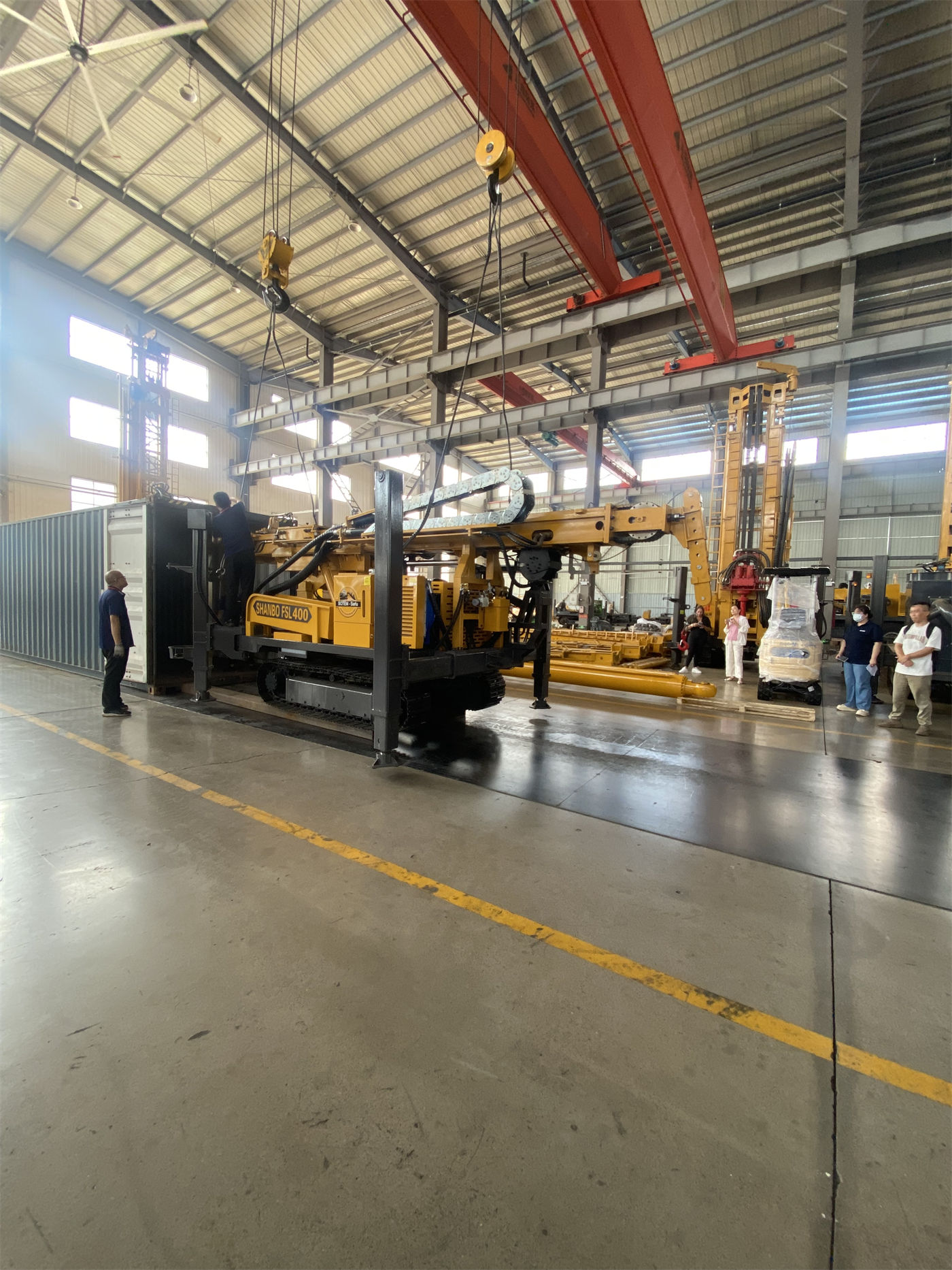
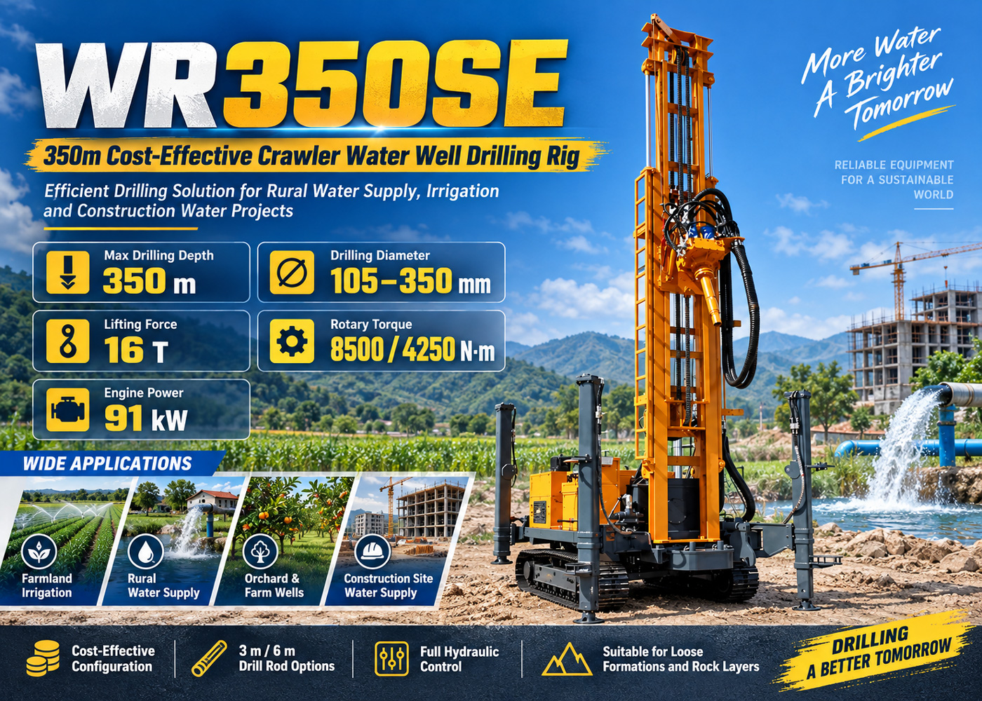
The WR350SE is HJH's 350-meter-class crawler water well drilling rig. The information gives its positioning as a combination of the S series and E series: the S series emphasizes compatibility with longer drill pipes and fewer pipe connections, while the E series emphasizes a balance between commonly used functions and procurement cost. The correspondence between its retained capability items and the constraint dimensions of conventional water well projects is as follows.
| Work constraint | Corresponding item in WR350SE information | Significance for selection |
|---|---|---|
| Target well depth | Maximum drilling depth 350 m | Covers conventional water wells in the 300-meter range and leaves some margin for water exploration |
| Completed well diameter | Drilling diameter 105–350 mm | Different completed well designs can be made according to well casing, submersible pump, and expected water yield |
| Drill pipe configuration | Supports 3 m / 6 m drill pipes, recommended diameters 89 / 102 mm | 3-meter drill pipes suit projects with transport and site restrictions; 6-meter drill pipes reduce the number of connections |
| Drill string handling | Lifting force 16 T, auxiliary winch 1.1 T (2.5 T optional) | Corresponds to 350-meter-class tripping, DTH hammer recovery, and some casing operations |
| Rotation and diameter matching | Dual-condition torque 8500 / 4250 N·m, corresponding to maximum rotation speeds 80 / 160 r/min | Low speed and high torque for larger diameters or hard rock sections; high speed for stages with lower resistance |
| Formation and process connection | Suitable for loose formations and rock formations; can be equipped with medium- and high-pressure DTH hammers, working air pressure 1.2–3.5 MPa | Mud rotary drilling or casing for upper soil layers; switch to DTH hammer after entering rock formations |
| Site access and relocation | Overall weight approximately 7.5 T, dimensions approximately 5.78 × 1.7 × 2.25 m, travel speed approximately 2.5 km/h | Easier to arrange transport and relocation between townships than large deep-well equipment |
This table illustrates the correspondence between capability items in the information and work objectives; it is not a conclusion that "every item is just sufficient." Whether it is sufficient also depends on the specific project's diameter, formation, and matching conditions.
Whether to Choose 3-Meter or 6-Meter Drill Pipes Depends on Transport and Site
The WR350SE supports both 3-meter and 6-meter drill pipes, which is a feature distinguishing it from models with a single drill pipe configuration. The choice between the two lengths is not about the equipment itself but about project conditions:
- For projects with ordinary transport conditions and limited construction sites, 3-meter drill pipes are lighter per piece and require less space for connections, making relocation and layout within the hole location more flexible.
- For projects that need to complete longer footage in a day and have relatively concentrated hole locations, 6-meter drill pipes reduce the number of connections, and the auxiliary time occupied by making and breaking drill pipe connections is correspondingly reduced.
It should be noted that 6-meter drill pipes reduce the number of connections, which is not equivalent to increasing actual footage speed in real rock formations. The reference drilling efficiency given in the information is 10–35 m/h; actual results depend on lithology, drilling tools, air compressor, and operating experience. Understanding drill pipe length as an efficiency commitment is a common deviation during selection.
Dual-Condition Torque Is Not a Two-Speed Gearbox
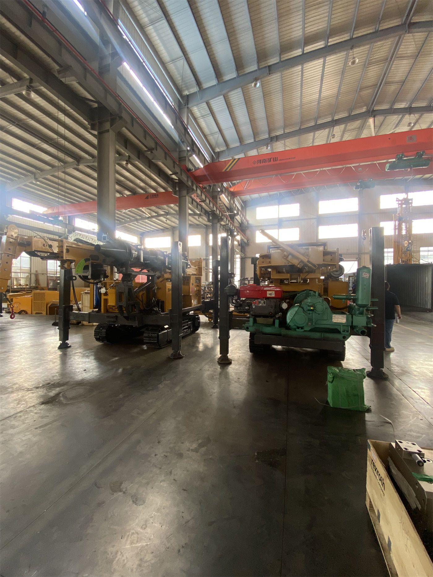
The two torque values of 8500 / 4250 N·m in the information correspond to maximum rotation speeds of 80 / 160 r/min. The low-speed high-torque condition suits larger diameters, higher resistance, or hard rock drilling; the higher-speed condition suits drilling stages with lower resistance. It is a configuration of two working conditions, not two gears in the driving sense. On site, adjustments must be made according to cuttings return, torque changes, and bit condition, and it cannot simply be understood as "shifting gears will increase speed."
Air Supply Matching Is an Often Underestimated Condition
When using DTH hammer drilling, the WR350SE recommends a working air pressure of 1.2–3.5 MPa and an air consumption of 16–55 m³/min. These two values indicate the range that can be matched on the equipment side; air compressor selection must still be combined with hole diameter, drill pipe, DTH hammer specifications, rock hardness, and construction altitude. Insufficient air volume will cause poor cuttings removal, while excessive configuration increases equipment and fuel costs. If the project is mainly mud rotary drilling in upper soil layers, the priority for matching mud pumps and centrifugal pumps will be higher than for air compressors; if stable power is lacking, generators must also be included in configuration considerations. In the information, mud pumps, centrifugal pumps, generators, and foam pumps are all optional configurations; selecting according to working conditions can avoid unnecessary procurement investment.
Applicable Boundaries: Which Conditions Push This Equipment Class Beyond the Edge
350-meter-class equipment covers conventional water wells of medium depth. The following situations require separate judgment and cannot be concluded solely based on the drilling depth figure:
- Design well depth approaching or exceeding 350 m: As hole depth increases, drill pipe weight and borehole wall friction rise simultaneously, and the lifting force margin narrows. Calculations should be made in combination with the drill string assembly and formation stability.
- Completed well diameter long-term near the 350 mm upper limit: Large diameters place higher demands on rotary torque, cuttings removal air volume, and wall stabilization measures, and must be evaluated according to actual diameter and lithology.
- Thick upper unstable hole sections: Fractures, broken zones, and air leakage conditions may cause block falling, stuck drilling, and abnormal cuttings removal. Casing configuration and auxiliary measures such as foam should be considered in advance; foam pumps are optional configurations.
- Poor site bearing capacity or slopes beyond the information range: The maximum climbing angle reference given in the information is 21°. Travel risks should be reduced on wet and slippery roads and soft soil areas, and pads should be used under the outriggers.
These boundaries are not conclusions that the equipment "cannot be used," but reminders to verify conditions clearly before quotation and production scheduling.
Several Matters to Confirm Before Site Access
Conventional water well projects are usually scheduled by hole location, and the cost of supplementing conditions after equipment arrives is relatively high. The following matters are recommended to be confirmed before commencement:
- Local hydrogeological data, including the approximate depth of the target aquifer and the position of the completed well section;
- The completed well diameter corresponding to well casing diameter, submersible pump specifications, and expected water yield;
- The thickness of upper loose layers and the wall stabilization method, and whether casing is needed and its specifications;
- The matching of air compressor air volume and pressure with DTH hammer specifications, as well as the influence of construction altitude;
- The width of roads to hole locations, ground bearing capacity, relocation routes, and space for deploying outriggers;
- The choice of drill pipe length and its coordination with transport vehicles and on-site connection space.
The WR350SE information covers drilling depth, hole diameter, drill pipe, torque, lifting force, air supply range, and overall transport dimensions, but it does not provide geological adaptability conclusions for specific projects. Final drilling efficiency, drilling depth, and completed well results should be based on on-site working conditions, and selection conclusions need to be formed after the above conditions are verified.