












Irrigation wells beside village roads, water supply wells deep in orchards, and production wells inside livestock farm fences—well positions are often not on open ground. Whether the equipment can drive up next to the hole position, whether the outriggers can be deployed, and whether the transport vehicle can turn around when moving from one completed well to the next—these things determine before drilling starts whether the project can proceed as planned. Mini crawler drills are used to handle such sites, and what they mainly provide is room for entry and positioning, but as the body becomes smaller, the range of processes they can cover also narrows. These two sides need to be considered together.
This article is based on public information about the WR220SE and focuses on three questions: which specific site constraints correspond to a compact body; under what formation conditions water drilling and air drilling should each be considered; and what needs to be confirmed before starting work regarding air supply, drilling tools, and well completion matching. Content outside the scope of these three questions, and parts not covered by the data, will be noted separately in the text.
First, the site: what specific margins does a small body provide
The WR220SE has overall dimensions of approximately 3950 × 1750 × 2250 mm, an overall weight of approximately 4.7 T, and a loading width of 2.6 m. These numbers alone do not explain the issue; on site they correspond to three things.
Hole position accessibility
Village roads, orchard paths, field edges, and courtyards often have limited passage width and turning room. An overall width of 1.75 m and an overall weight of 4.7 T means the equipment has more room to attempt access on narrower passages and sites with ordinary load-bearing conditions. The data states that applicable ground includes village roads, farmland, orchards, gravel ground, and generally uneven sites. This is the first layer of basis for judging whether entry is possible.
Positioning at the hole location
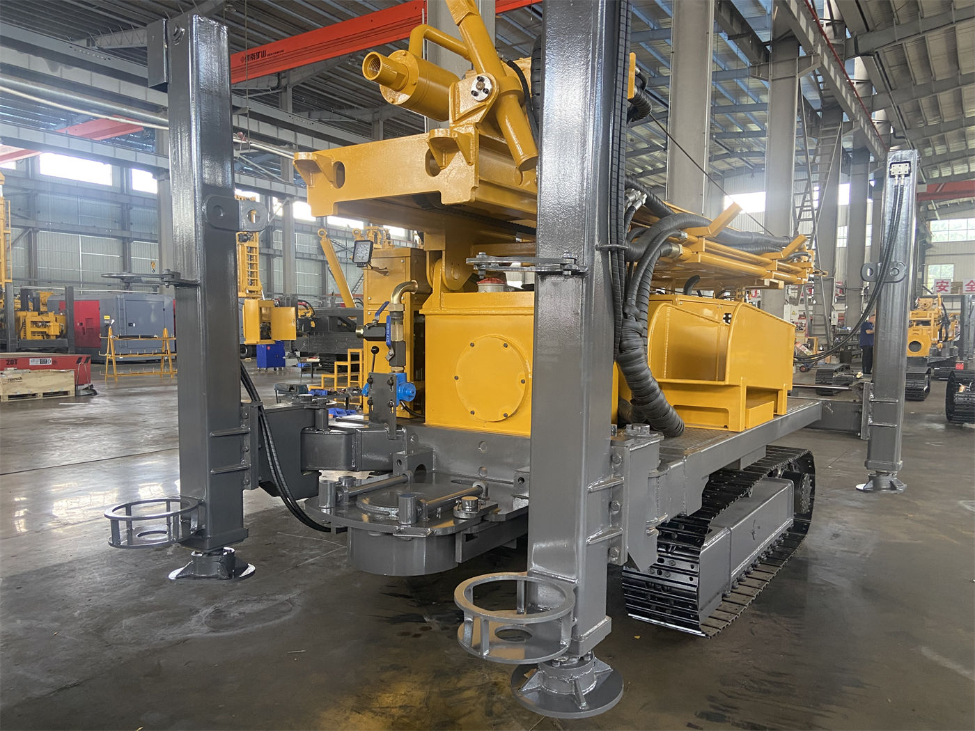
The crawler chassis has a travel speed of approximately 2.5 km/h and a maximum gradeability reference of 30°. After reaching the hole position, the 1.4 m outrigger stroke is used for support and leveling. On soft ground, pads should be added to prevent the outriggers from sinking. The deployment range allowed by the site, ground bearing capacity, and slope determine whether the outriggers can truly support the machine stably, not just whether the equipment can park inside.
Moving between holes and relocating
Farmland irrigation and orchard projects often involve multiple consecutive wells, with frequent moves between holes. The 2.6 m mast, 3.3 m single feed, and compatibility with 1.5 m, 2.0 m, and 3.0 m drill rods—this combination targets the pace of frequent relocation and daily water well construction for small crawler drills. The mast height is not high, so requirements for overhead clearance and passage during relocation are relatively small, but the loading tie-down points and mast transport position still need to be confirmed each time.
Next, the process: water-air dual-purpose is not a universal switch
The WR220SE supports water-air dual-purpose drilling, with a maximum drilling depth of 220 m, a hole diameter of 140–254 mm, a rotary torque of 3400–4700 N·m, and a rotary speed of 45–70 rpm. Water-air dual-purpose means selecting the more suitable process according to the formation, not that the same set of parameters can handle all hole sections at the same time.
Soil, clay, and loose overburden
For such hole sections, the direction given by the data is to focus on hole stabilization and cuttings removal. Sand layers and gravel layers are also prone to hole collapse, drilling tool burial, and hole diameter enlargement, especially when the groundwater level is high. Priority should be given to hole wall protection and casing follow-up. When necessary, water drilling or other hole stabilization methods should be used. The data explicitly does not recommend relying solely on air drilling to quickly pass through.
Weathered rock and relatively intact rock formations
After entering weathered rock or relatively intact rock formations, a down-the-hole hammer and air compressor can be matched for air drilling. Drilling speed in weathered rock is usually faster, but the hole wall structure may be unstable. The feed speed needs to be controlled according to falling blocks, diameter reduction, and water return conditions, and casing or hole cleaning measures should be taken promptly. After entering relatively intact rock, impact, rotation, and cuttings removal must remain coordinated.
Fractured zones and fissured formations
Such hole sections may experience air leakage, falling blocks, stuck drilling tools, or abnormal cuttings removal. The handling direction given by the data is to reduce the feed speed, maintain continuous hole cleaning, and observe changes in air pressure and water return. When the fractured zone is thick, casing or sectional treatment can be used. Whether to use it and to what level still needs to be judged according to the actual hole section.
During air drilling, the air compressor is a separate matching issue
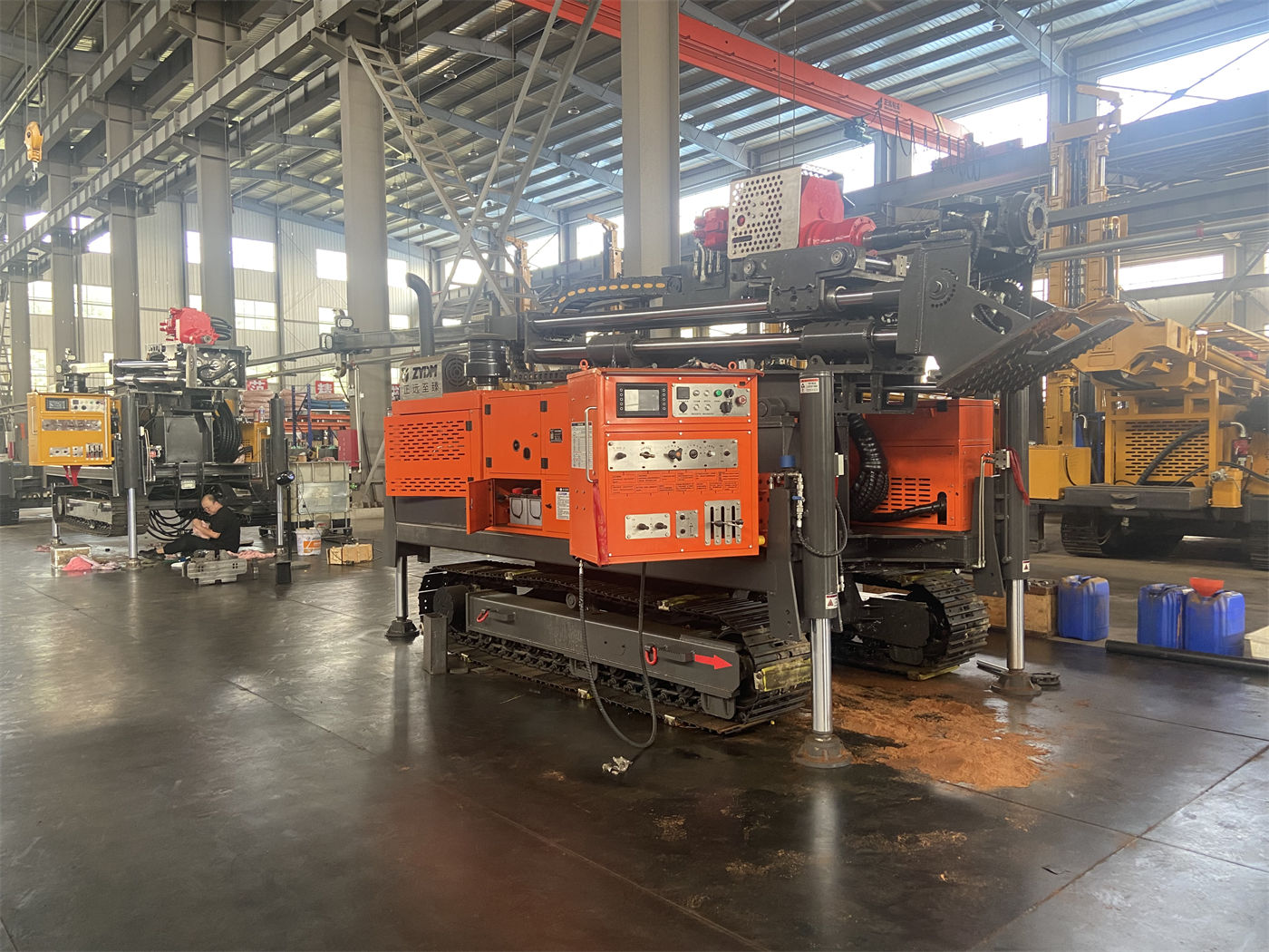
The reference working air pressure given by the data is 1.7–2.5 MPa, and the air consumption is 17–31 m³/min. The purpose of these two values is to remind that when using a down-the-hole hammer for drilling, the air compressor is not an accessory but a condition that determines whether this process can be established. The data also states that when the hole diameter increases, the rock formation becomes harder, or the altitude rises, the requirement for air compressor displacement will be higher. It should be selected according to the actual down-the-hole hammer specifications, and pressure alone should not be the only consideration.
In other words, the drilling depth and torque of the drill itself cover a certain range, but that does not mean air drilling is already feasible at a specific hole position. Air compressor displacement, down-the-hole hammer specifications, bit diameter, and target hole depth must be checked together. This item needs to be confirmed with the air supply equipment supplier and the drilling tool supplier before being decided.
Drill string and well completion matching: hole diameter determines more than just the bit
The drilling diameter of 140–254 mm can be selected according to the well casing specifications, submersible pump size, and expected water yield. This means the hole diameter is not fixed first and then a bit is found; rather, it is derived backward from the well completion design: how large the well casing is, how large the pump is, and how much water yield is expected determine how large the hole should be opened; and how large the hole is opened in turn affects the drilling tool combination and cuttings removal method.
The data mentions that Φ76 or Φ89 drill rods can be configured. Different formations and hole diameters should be matched with different drilling tools. Especially for water-air dual-purpose projects, the main formation types and construction methods should be clarified in advance. During well completion, filter pipes and sealed sections also need to be reasonably set according to the aquifer position. The data does not elaborate on specific methods for this part, and it belongs to content that needs to be separately confirmed according to local hydrogeology and well completion design.
Lifting force and rotation: routine operations can be covered, but abnormal handling cannot rely on forced pulling
The 13 T lifting force corresponds to routine drill rod tripping, drilling tool handling, and some casing operations. The boundary for this is stated relatively clearly in the data: if drilling resistance continues to increase, water return suddenly decreases, or the drilling tool rotates poorly, the hole wall, cuttings removal, and drill rod condition should be checked first, and then measures such as hole cleaning, slow lifting, or casing should be taken. It is not recommended to directly use the maximum lifting force for forced pulling. This is a usage boundary, not an operating detail, but it determines what the equipment can and cannot do when abnormalities occur in the hole.
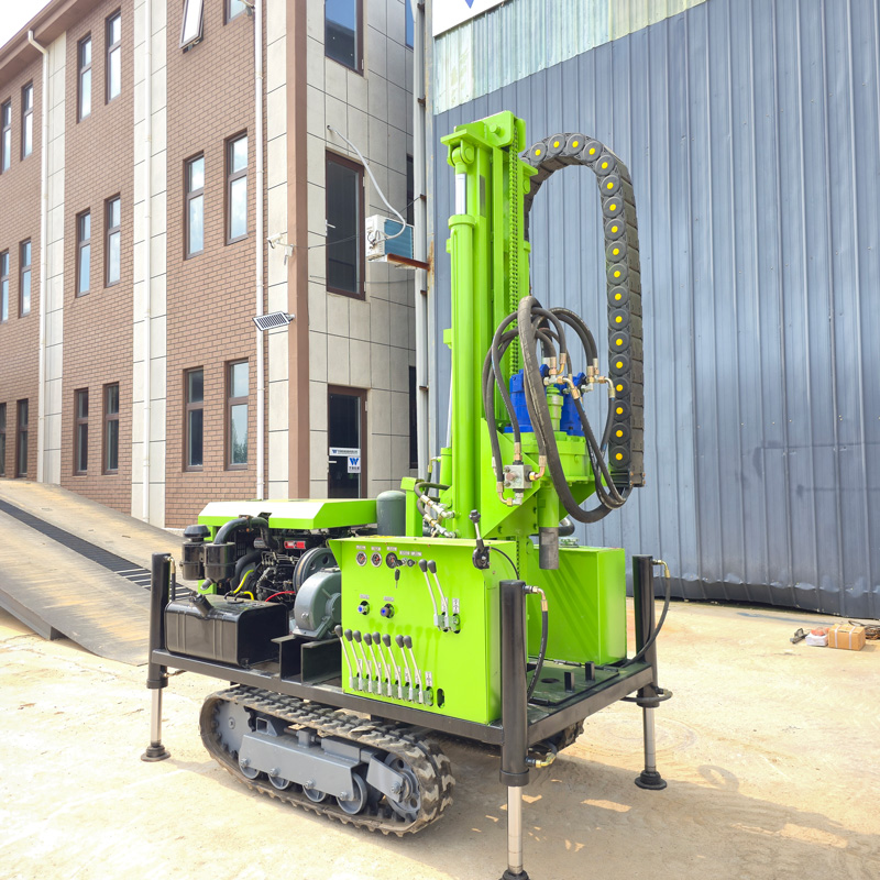
The rotary torque of 3400–4700 N·m and rotary speed of 45–70 rpm can, according to the data, cover most conventional 220-meter-class water well projects. Stable rotation speed can be maintained in intact rock formations, and rotation speed and feed should be appropriately reduced in fractured zones or when resistance increases. The fast lifting speed of 30 m/min and fast feed speed of 60 m/min are used for power head movement and drill rod operations to reduce non-drilling time. The data reminds that the fast feed speed cannot be directly understood as the actual drilling speed; penetration efficiency still depends on formation hardness, hole diameter, drilling tool wear, air compressor capacity, and operating method.
Applicable boundaries and matters requiring advance confirmation
Several boundaries can be determined from the data: maximum drilling depth of 220 m, drilling diameter of 140–254 mm, water-air dual-purpose process selection according to formation, and routine operations covered by 13 T lifting force and 3400–4700 N·m torque. The data also gives a general applicable premise: actual drilling efficiency, drilling depth, and well completion results should be based on on-site working conditions.
Matters not covered by the data and requiring separate confirmation during the selection stage include:
- Whether the specific site can satisfy outrigger deployment and ground bearing capacity, especially on soft soil, backfill, and slopes;
- The matching result between air compressor displacement and the selected down-the-hole hammer, hole diameter, and target hole depth;
- The correspondence between well casing specifications, submersible pump size, and the 140–254 mm hole diameter;
- The allocation ratio of water drilling and air drilling in the main formation combination, and the number of casing follow-up stages;
- The relocation route between consecutive wells, transport vehicles, and loading tie-down conditions.
Without confirming these matters, it is impossible to judge whether this equipment is just sufficient, still has margin, or is already close to the boundary for a specific project. The entry flexibility gained from a mini crawler drill is real, but the other side of flexibility is a relatively limited process coverage. During selection, site conditions and formation conditions should be placed in the same checklist, rather than comparing only drilling depth figures.