












In the WRT1200 parameter table, the 61 T lifting force is often singled out for horizontal comparison. But in the publicly available data on this site, this figure is never isolated: below it are the recommended 127 mm drill pipe and 3 m/6 m rod lengths, beside it are the 24000/12000 N·m dual-condition torque and 75/150 r/min dual speed, toward deep-hole operations it also connects to 13 T axial pressure and 7/13 m feed stroke, and toward DTH conditions it connects to 1.65–8 MPa working air pressure and 16–120 m³/min air consumption. Looking at 61 T alone would miss the mutually limiting relationships between it and other values; reading back from it, however, reveals how the parameters of this 1200-meter class truck-mounted straight-mast water well drilling rig are organized.
The following unfolds in the order of "lifting force extending in four directions," not repeating the parameter table item by item, but only explaining what each group of values constrains and which judgments the data itself does not provide a basis for.
Lifting force is not an isolated indicator; it is first bound to drill string specifications
The data gives a recommended drill pipe diameter of 127 mm, with drill pipe lengths supporting 3 m or 6 m. Placing the 61 T lifting force in this context makes its meaning more specific: as hole depth increases, the drill pipe's own weight, casing weight, and borehole wall friction all rise simultaneously. The lifting force needs to cover the entire package of "drill string weight + downhole friction + dynamic loads during tripping," not just the weight of a certain section of drill pipe.
The advantage of 6 m drill pipe is fewer connections, while 3 m drill pipe is more flexible in transport, manual coordination, and restricted sites. The two rod lengths do not have exactly the same demand for lifting force: at the same hole depth, different numbers of connections mean different time organization for tripping and different bottomhole assemblies. The fact that the data writes drill pipe diameter, rod length, and lifting force in the same capability description is itself a reminder that these three should be viewed together.
The data does not provide a drill string weight calculation table for different hole depths, nor does it give recommended values for borehole wall friction. Therefore, whether "61 T is sufficient at a specific well depth" cannot be judged from the parameter table alone; it needs to be calculated separately according to the actual drill string assembly.
Looking horizontally from lifting force, it is the dual-condition and dual-speed configuration of torque
The maximum torque of the WRT1200 rotary system is 24000/12000 N·m, corresponding to a 75/150 r/min dual-speed configuration. The data describes the division of the two gears fairly directly: low speed and high torque are more suitable for large-diameter, hard rock, and high-friction hole sections, while the high-speed gear is suitable for stable formations with less resistance.
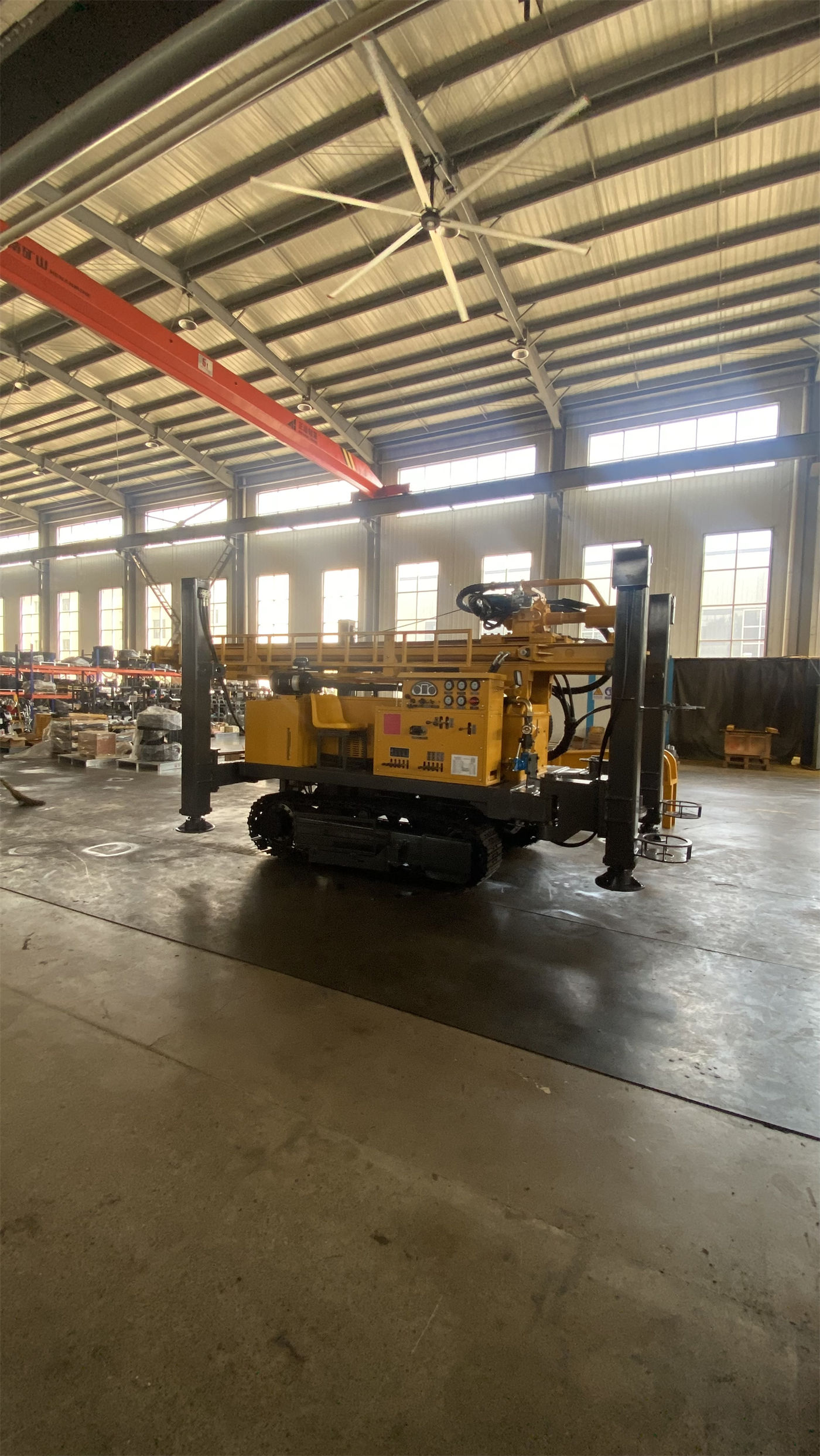
Although lifting force and torque act in different directions, they are often tested simultaneously by the same hole condition during deep-hole operations. When downhole friction rises, rotation requires greater torque and tripping requires greater lifting force; the situation where both rise at the same time mostly occurs in large-diameter, hard rock, or poorly stable borehole sections. The data recommends switching conditions in a timely manner according to drill string load, cuttings return, and torque changes, but does not give specific thresholds for switching by hole diameter or rock formation.
| Parameter | Data Value | What to also look at when reading this item |
|---|---|---|
| Maximum lifting force | 61 T | Recommended drill pipe 127 mm, 3 m/6 m rod length |
| Axial pressure | 13 T | Opposite direction to lifting force, both belong to the feed system |
| Rotary torque | 24000/12000 N·m | 75/150 r/min dual-speed configuration |
| Feed stroke | 7/13 m | Selected according to final configuration, subject to supplier technical confirmation |
| Drilling diameter | 105–900 mm | Increased hole diameter drives drill string load, casing weight, and cuttings removal demand |
| Maximum drilling depth | 1200 m | A capability limit description, not a construction record for a specific well |
Axial pressure and lifting force are two directions of the same feed system
The 13 T axial pressure appears alongside the 61 T lifting force in the data. These two figures describe the output capability of the feed system in different directions: lifting force corresponds to tripping, DTH hammer recovery, and some casing operations, while axial pressure corresponds to the pressure applied to the bottom of the hole during drilling.
The actual effect of axial pressure depends on the bit type and rock formation conditions. The data does not provide recommended axial pressure values for different rock formations. It is also worth noting that the data explicitly states: if tripping resistance is abnormal, the hole should first be cleaned and the condition of the borehole wall, drill string, and sediment judged; one should not simply rely on maximum lifting force to pull forcefully. The implication is that 61 T is the equipment's output limit, not a solution for stuck pipe.
The 7/13 m feed stroke affects the drill string organization method, not the magnitude of lifting force
The data gives a feed stroke of 7/13 m, selected according to the final configuration, and notes that the formal configuration should be subject to supplier technical confirmation data. A longer stroke can reduce the frequency of power head return and drill pipe handling, making it more suitable for deep-hole projects pursuing continuous drilling efficiency; the 7 m configuration more easily balances overall machine structure and site adaptability.
It is important to distinguish here: the feed stroke changes the rhythm of connections and returns, not the rated values of lifting force and axial pressure. Understanding the 13 m stroke as "stronger lifting force" is a misreading. Stroke is a parameter at the operational organization level, while lifting force and axial pressure are parameters at the output capability level.
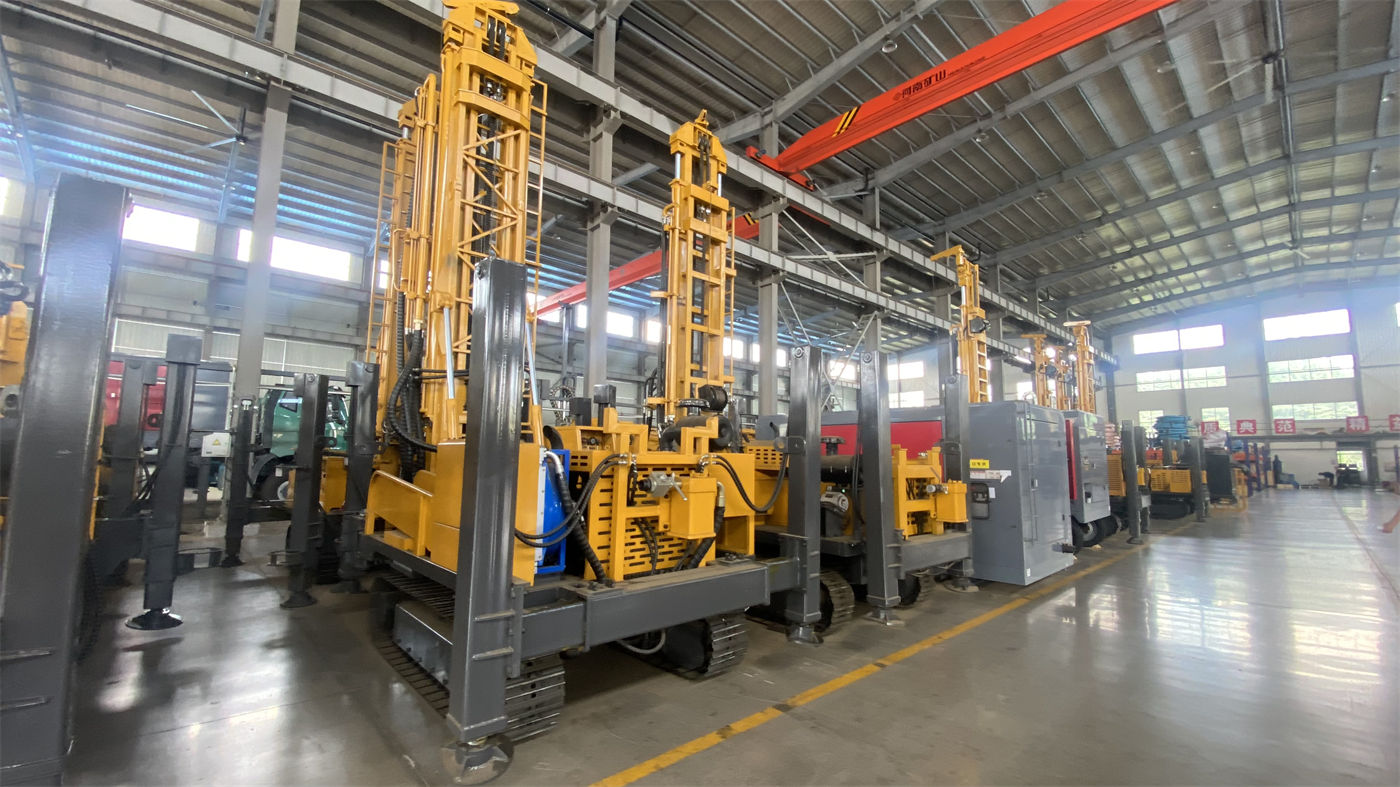
After entering DTH conditions, air pressure and air consumption must also be considered beyond lifting force
The data states that when using DTH hammer drilling, the recommended working air pressure is 1.65–8 MPa and air consumption is 16–120 m³/min. For 1200-meter class deep holes, large diameters, and hard rock conditions, the air compressor pressure and displacement requirements are very high. Meeting pressure alone while displacement is insufficient can still lead to insufficient impact, difficult cuttings removal, and bottomhole sediment accumulation.
The relationship between this set of parameters and lifting force is easily overlooked: poor cuttings removal increases bottomhole sediment, which in turn raises downhole friction and ultimately reflects on the lifting force demand during tripping. The data mentions that once cuttings return decreases, air pressure fluctuates, or rotary resistance is abnormal, one should promptly judge air leakage, sediment accumulation, or bit wear. In other words, abnormal lifting force demand may originate from upstream air supply and hole cleaning, not the lifting system itself.
Putting the parameter chain back into the overall machine conditions
The WRT1200 has an overall weight of about 32 T, transport dimensions of about 11.5 × 2.25 × 3.2 m, and can be equipped with 220 kW or 264 kW diesel power. It uses a straight-mast structure rather than a telescopic mast. The data explains this as a more direct overall force path, suitable for long-term high-torque rotation, heavy drill string tripping, and casing operations; the trade-off is a more fixed transport profile, so road height limits, entry space, and site clearance should be confirmed before construction.
The drilling diameter range of 105–900 mm also belongs to the same chain of values: a larger hole diameter facilitates larger well casing and submersible pumps, but simultaneously increases drill string load, casing weight, cuttings removal demand, and air compressor load. As hole diameter increases, the requirements for lifting force, torque, and air supply capacity change together; there is no method of adjusting only one of them to cover all hole diameters.
Judgments the data can support and cannot support
- Can support: The 61 T lifting force, 127 mm drill pipe, and 3 m/6 m rod length belong to the same configuration relationship; lifting force and 13 T axial pressure correspond to the two directions of the feed system; torque is divided into two gears at 75/150 r/min, corresponding to different hole sections.
- Can support: Under DTH conditions, the air pressure of 1.65–8 MPa and air consumption of 16–120 m³/min must be used together; if pressure is met but displacement is insufficient, cuttings removal problems may still occur.
- Cannot support: The data does not provide a margin calculation method for 61 T at a specific well depth, specific drill string assembly, and specific hole diameter, nor does it give reference values for borehole wall friction.
- Cannot support: The data does not explain which specific project conditions the 7 m and 13 m feed stroke configurations correspond to, only mentioning that the selection is based on the final configuration and subject to supplier technical confirmation data.
Items recommended for written confirmation before purchase
The following items are not conclusively determined in the data and are recommended to be checked in writing during the technical confirmation stage:
- Whether the final feed stroke is 7 m or 13 m, and the specific impact of that choice on overall machine dimensions and transport profile;
- The main hole diameter, rock formation hardness, and auxiliary system load conditions corresponding to the 220 kW and 264 kW power options;
- For the project's actual hole diameter and planned well depth, calculate the matching of lifting force and torque according to the intended drill string assembly;
- The air compressor pressure and displacement plan under DTH conditions, as well as the specification requirements for matching air hoses;
- Whether entry conditions such as road height limits, bridge load capacity, turning radius, site bearing capacity, and overhead obstacles meet the transport profile of the straight-mast structure.
Reading the 61 T lifting force back into the parameter chain does not yield a single conclusion of "how deep this equipment can drill," but rather a set of mutually limiting relationships: it is bound to drill pipe specifications, together with torque, axial pressure, and feed stroke forms the feed and rotary system, and is indirectly connected to DTH air supply parameters through cuttings removal effects. The data can explain how these values are organized together, but whether they are sufficient for a specific well still needs to be calculated separately according to the drill string assembly and hole conditions.