












When "telescopic mast" is discussed on a water well construction site, the conversation often stops at transport height and deployment method. But what mast telescoping really touches is the drill pipe handling and tripping step: how long the effective stroke is after the mast is deployed determines how far the power head can push in one pass; how long a single drill pipe is determines how often work must stop to make a connection. If these two do not match, the telescopic structure has limited effect on the drilling rhythm. Using the public information on the WR200SE as a thread, this article places "telescopic" back into the operating sequence of 200 m-class water well construction, explaining which work step it corresponds to, what supporting conditions are needed, and which judgments still have to be made on site.
First, see which segment of the operating sequence "telescopic" falls into
For a crawler water well drilling rig to drill a well, it roughly goes through these stages: site entry and positioning, outrigger leveling, hole opening, normal drilling, pipe connection, tripping, casing running and well completion, and hole changeover and relocation. A telescopic mast does not change the way the drill bit breaks rock during drilling, nor does it directly determine how deep the rig can drill; what it affects is the transition of the mast from transport state to working state, and the stroke space available to the power head inside the mast after that transition.
Therefore, to judge whether "telescopic" is useful, two things must hold at the same time: during transport, the mast can be shortened to reduce height and lower the requirements on roads and sites; during operation, after the mast is deployed, the stroke can match the selected drill pipe length so that the number of pipe connections and trips falls within an acceptable range. If only the former is met, it is a transport feature; only when both are met does it enter the work-step level.
Several items in the WR200SE information directly related to this work step
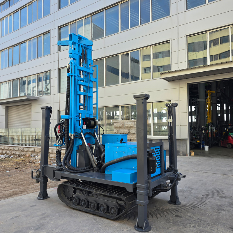
The WR200SE is a 200 m-class crawler water well drilling rig, with a maximum drilling depth of 200 m, a hole diameter of 140–254 mm, and a Yuchai 58 kW engine. The public information related to the mast and feed includes: telescopic mast, single feed length 3.3 m, compatible with 1.5 m, 2.0 m and 3.0 m drill pipes, fast lifting speed 30 m/min, fast feed speed 60 m/min, and lifting force 13 T. The overall weight is about 4.7 T, dimensions about 3950 × 1750 × 2250 mm, travel speed about 2.5 km/h, maximum gradeability reference 30°, and outrigger stroke 1.4 m.
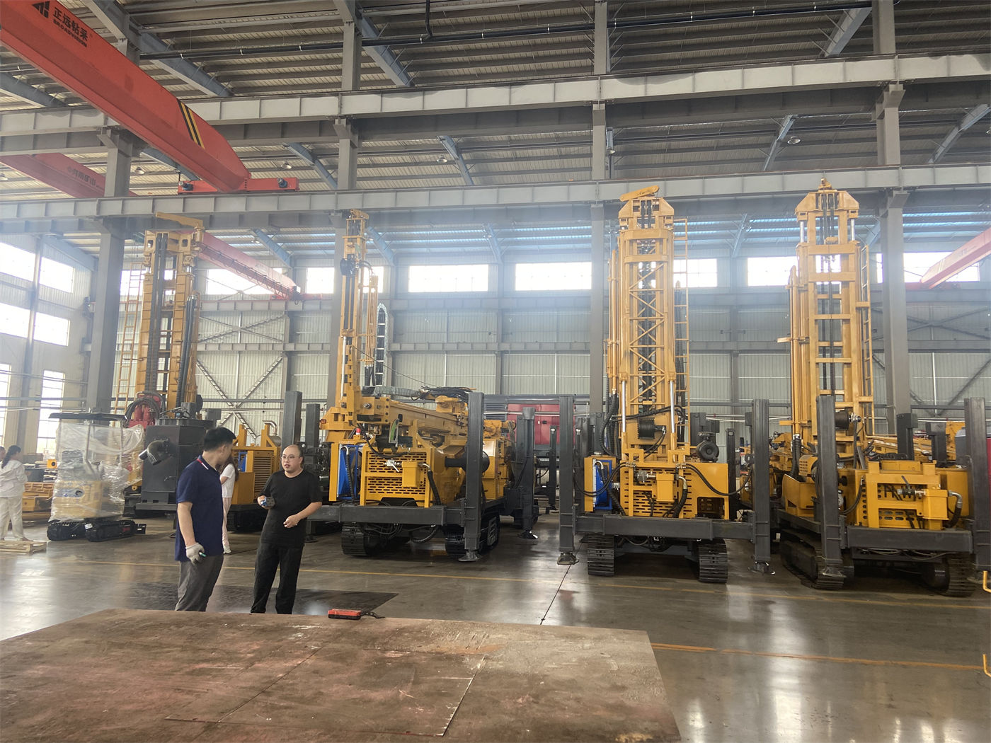
In this set of data, "single feed length 3.3 m" and "compatible with 3.0 m drill pipes" only make sense together: if 3.0 m drill pipes are selected, one feed stroke can cover the length of one drill pipe, and the number of pipe connections is counted at 3 m per single pipe; if 1.5 m drill pipes are selected, the number of pipe connections at the same hole depth will multiply, but the weight per single pipe is lighter, making handling and make-up easier. The role of the telescopic mast here is to allow the mast to be shortened during transport and deployed during operation to accommodate this stroke, rather than raising the drilling depth from one value to another.
What mast stroke, drill pipe length and lifting speed each govern
| Information item | Corresponding work step | What cannot be inferred from it |
|---|---|---|
| Telescopic mast, single feed length 3.3 m | Mast transport height and effective stroke after deployment, affecting the drill pipe length covered by a single feed | Cannot infer actual drilling speed or completed well depth |
| Compatible with 1.5 / 2.0 / 3.0 m drill pipes | Single drill pipe length determines connection frequency and single-pipe handling weight | Cannot infer that a certain drill pipe combination is suitable in all formations |
| Fast lifting 30 m/min, fast feed 60 m/min | Power head movement and drill pipe operations in non-drilling state, affecting auxiliary time | Cannot be equated with penetration rate in rock formations |
| Lifting force 13 T | Tripping, drill pipe handling and some casing operations | Cannot be used as a basis for forcibly pulling stuck drilling tools |
The two values of fast lifting and fast feed are often misread as drilling efficiency. The information itself states clearly that they are used for power head movement and drill pipe operations in non-drilling state, and their role is to compress the time of auxiliary actions such as loading and unloading drill pipes and lifting and lowering drilling tools. The actual penetration in rock formations depends on lithology, down-the-hole hammer, drill bit and air compressor capacity; the reference drilling efficiency of 10–35 m/h given in the information is only a range and cannot be directly applied to a specific project.
Which drill pipe length to choose depends on transport, site and labor organization
3.0 m drill pipes reduce the number of pipe connections, but each single pipe is heavier, and the requirements for racking space and operating space after mast deployment are higher; 1.5 m drill pipes are light and easy to handle, with low requirements on site and lifting gear, at the cost of a significantly increased number of handling operations at the same hole depth. 2.0 m lies between the two. This trade-off is not a question of equipment capability but of construction organization: when hole positions are scattered, relocations are frequent and on-site manpower is limited, the handling advantage of light drill pipes may be more important than reducing pipe connections; when hole positions are concentrated, single wells are deeper and a continuous drilling rhythm is pursued, the value of long drill pipes in reducing auxiliary actions is more obvious.
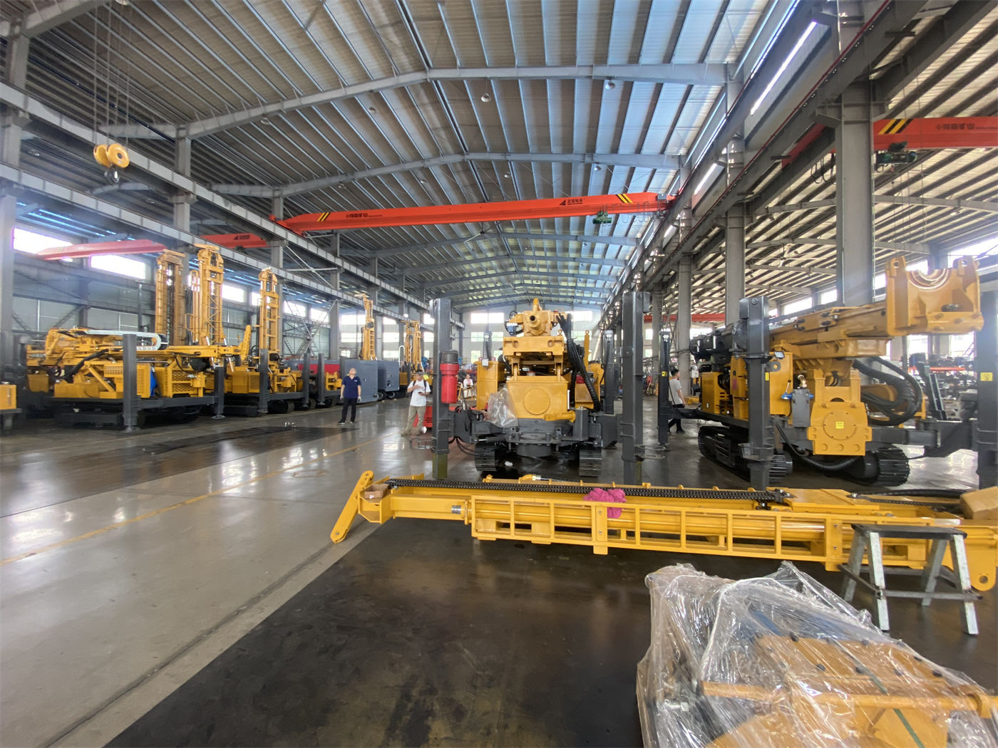
It should be noted that the information only gives the compatible drill pipe lengths and single feed length, and does not give a comparison of actual construction efficiency under different drill pipe combinations. Which one to choose still needs to be confirmed in light of the project's well depth distribution, transport vehicle conditions, on-site crew size and lifting method, and cannot be inferred from mast stroke alone.
Transport and site conditions brought by the telescopic structure
The WR200SE has an overall weight of about 4.7 T and dimensions of about 3950 × 1750 × 2250 mm, placing it in the range of small and medium crawler water well drilling rigs. The telescopic mast is shortened in transport state, and with this size and weight it is easier to arrange ordinary transport vehicles, and it is also suitable for water well construction teams with many hole positions and frequent relocations. The outrigger stroke of 1.4 m can be used for leveling on uneven ground, and the crawler chassis is suitable for rural roads, farmland and general unpaved sites.
But these are conditions, not conclusions. Mast retraction and deployment must be carried out according to operating procedures, and the fixing method must be confirmed before transport; after deployment on site, the load-bearing ground under the outriggers must be checked, and pads must be added on soft soil sites; when moving on slopes, the mast should be retracted to lower the center of gravity. The information gives a maximum gradeability reference of 30°, which is a reference value; whether a certain village road or field ridge can actually be passed depends on road surface adhesion, slope length and turning radius, and cannot be judged from an angle figure alone.
Which work steps "telescopic" cannot cover
A telescopic mast does not solve the wall protection problem of the upper loose layer. The information clearly notes that directly using a down-the-hole hammer in soil, clay, sand and gravel layers is not necessarily the best solution; loose overburden is prone to hole collapse, buried drilling tools and hole diameter enlargement, and the upper hole section should first be treated with casing, mud or other hole-stabilizing methods. No matter how reasonable the mast stroke is, this section of the process still has to be arranged separately.
It also does not solve air supply matching. The WR200SE reference working pressure is 1.7–2.5 MPa, air consumption 17–31 m³/min, and the air compressor must be selected according to hole diameter, down-the-hole hammer specifications, target hole depth, altitude and rock hardness. Insufficient air supply directly affects impact frequency, cuttings removal and drilling efficiency, which has nothing to do with whether the mast is telescopic. In addition, working conditions such as fracture zones, water inflow from aquifers, and alternating hard rock and weathered rock each have corresponding drilling tool and process adjustments, and the telescopic structure only handles the mast space among them.
Turn judgments into pre-start checklist items
- Whether the target well depth is within the 200 m coverage and whether the completed well diameter falls between 140–254 mm;
- Whether the drill pipe length is chosen as 1.5 m, 2.0 m or 3.0 m, and whether it matches the transport method, on-site manpower and single well depth;
- Whether the air compressor displacement and pressure can meet the selected hole diameter and down-the-hole hammer;
- Whether the height restrictions and turning conditions on the transport route and the hole position site allow the mast to be retracted for passage and deployed for operation;
- What hole-stabilizing method is used for the upper loose layer, and whether casing tools need to be provided;
- Whether the ground bearing capacity under the outriggers is sufficient, and whether pads are needed.
Among these items, the first two can be checked against the information, while the latter ones must be confirmed in light of the project site. What the telescopic mast changes is the transition of the mast from transport to operation, and the stroke space available to the power head after that transition; whether it truly reduces the pause in a certain work step depends on whether drill pipe selection, air supply matching and site conditions can keep up at the same time.