












Water supply wells or irrigation wells in hilly villages are rarely concentrated in one place. One well may be on open ground beside a village road, the next in an orchard halfway up a slope, and another in a narrow courtyard behind the village committee office. A single transfer distance is often only a few hundred meters to a few kilometers, but village road widths, curve radii, and courtyard plots in front of and behind houses repeatedly constrain equipment passage and setup. For the construction crew, transfer planning is not simply towing the machine to the next point; it is first determining which well sites can be entered, which can only be served by stopping at the road junction, and which components must be re-secured when changing boreholes.
What Such Projects Must Address First
The transfer pressure for dispersed well sites in hilly villages comes mainly from three areas: passage—whether village roads and unpaved field roads allow the equipment to travel on its own or be loaded onto a transport vehicle; setup—whether there is space beside the borehole to park, set up, and handle drill pipes; repetition—a project may have more than a dozen wells, and every borehole change repeats securing, inspection, and startup. Equipment selection therefore cannot look only at drilling depth; it must also consider whether overall dimensions, weight, travel method, and mast height match these constraints.
Only by looking at these matters separately can transfer planning have an order: first group well sites by passage conditions, then check whether the equipment's dimensions and weight fall within the margins of village roads and courtyard plots, and finally arrange the sequence of transport vehicles and material transfer. The following uses publicly available WR180E information to explain why a 180 m-class small crawler water well rig is worth including in comparison for such scenarios.
Overall Dimensions and Weight: Determining Whether Equipment Can Enter Village Roads and Courtyards with Minimal Disassembly
WR180E information states an overall weight of approximately 1.8 T and overall dimensions of approximately 3000 × 1300 × 1700 mm. In the context of hilly villages, these figures support two judgments: first, whether the equipment can be transferred by small transport vehicles; second, whether it can pass through village roads and the space in front of courtyard gates during transport or self-propelled travel.
An overall weight of 1.8 T means it does not depend on large flatbed trucks and heavy lifting. For projects with small individual wells and short distances between boreholes, the crew can load the equipment onto small transport vehicles for point-to-point transfer rather than traveling long distances on its own each time. The information also states that the machine is suitable for transfer between worksites using small transport vehicles, which corresponds to the common "short distance, high frequency" transfer rhythm in hilly village projects.
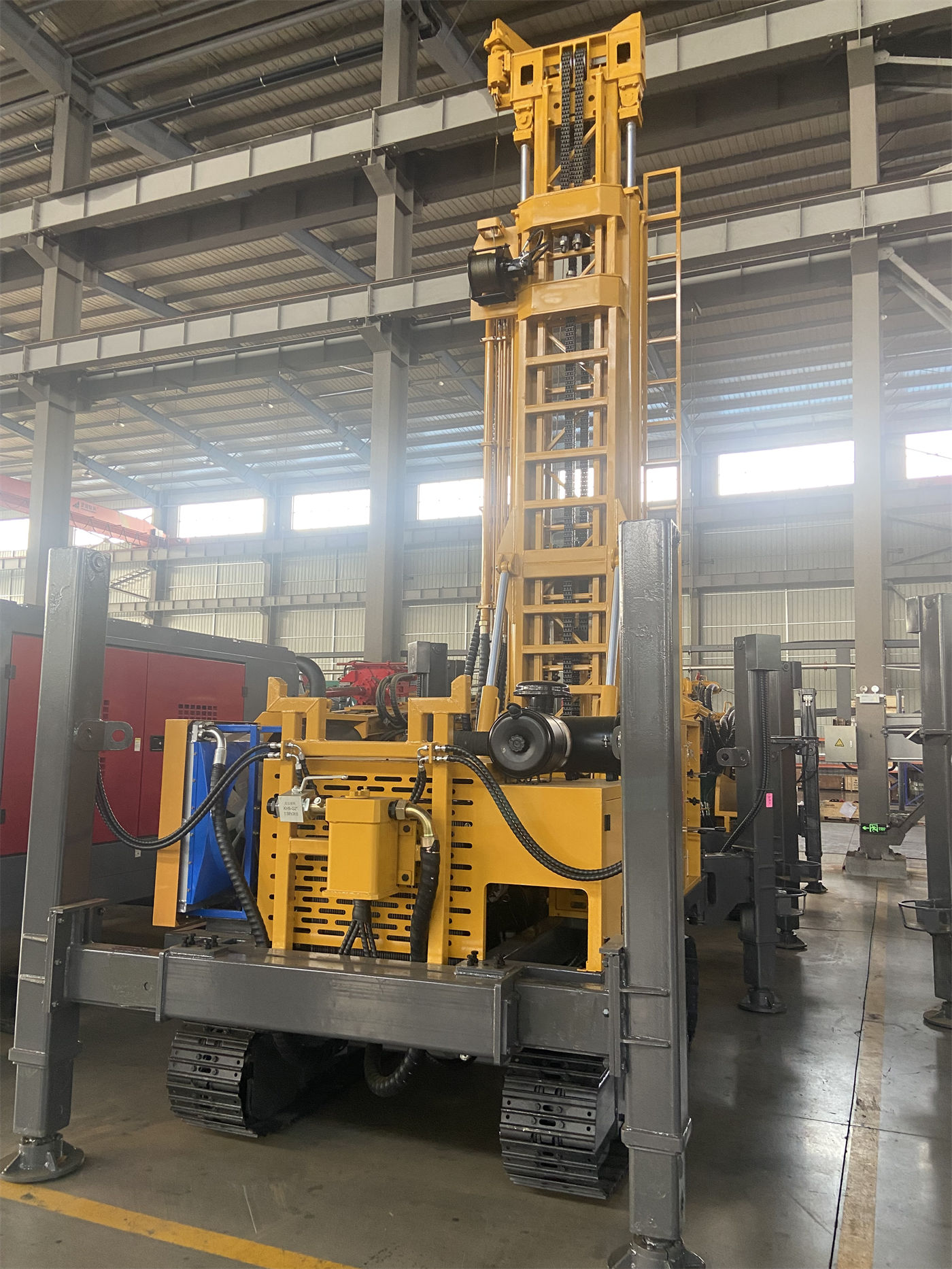
It should be noted that the information does not provide the specific load capacity, vehicle type, or securing method for transport vehicles, nor does it state village road width and slope limits. Whether it can actually travel and how it should be secured still need to be confirmed according to the on-site conditions of each road section and each transport vehicle. The 1300 mm body width is only the equipment's own dimension data and cannot be directly used to infer that it can pass through any village road.
Crawler Travel and 2.5 km/h: For Movement Within Borehole Sites and Short-Distance Adjustment
WR180E uses a crawler chassis, and the information gives a travel speed of 2.5 km/h. Between boreholes in orchards, at the ends of field ridges, and within courtyards, the equipment needs to move short distances and align with the borehole opening; the crawler chassis can handle this travel. 2.5 km/h is not a road travel speed; understanding it as the speed for site transfer and borehole adjustment is closer to the positioning in the information.
However, crawler travel does not mean it can self-transfer over long distances on any village road. Slopes and curves are common on hilly village roads, and the information does not provide climbing ability or ground pressure data, so it cannot be used to judge what kind of slope the equipment can handle. A more prudent approach in transfer planning is: use transport vehicles when distances between well sites are relatively long or road conditions are uncertain; consider crawler self-travel only when distances are short and the site is level.
1.5 m Mast: Lower Height Comes at the Cost of Rod Connection Frequency
WR180E has a mast height of 1.5 m. The information clearly states that the lower mast keeps the overall working height low and the transport volume small, making it suitable for space-limited scenarios such as courtyards, orchards, small worksites, and rural roads; it also notes that a shorter mast means drill pipe replacement frequency will be higher than with long-stroke models.
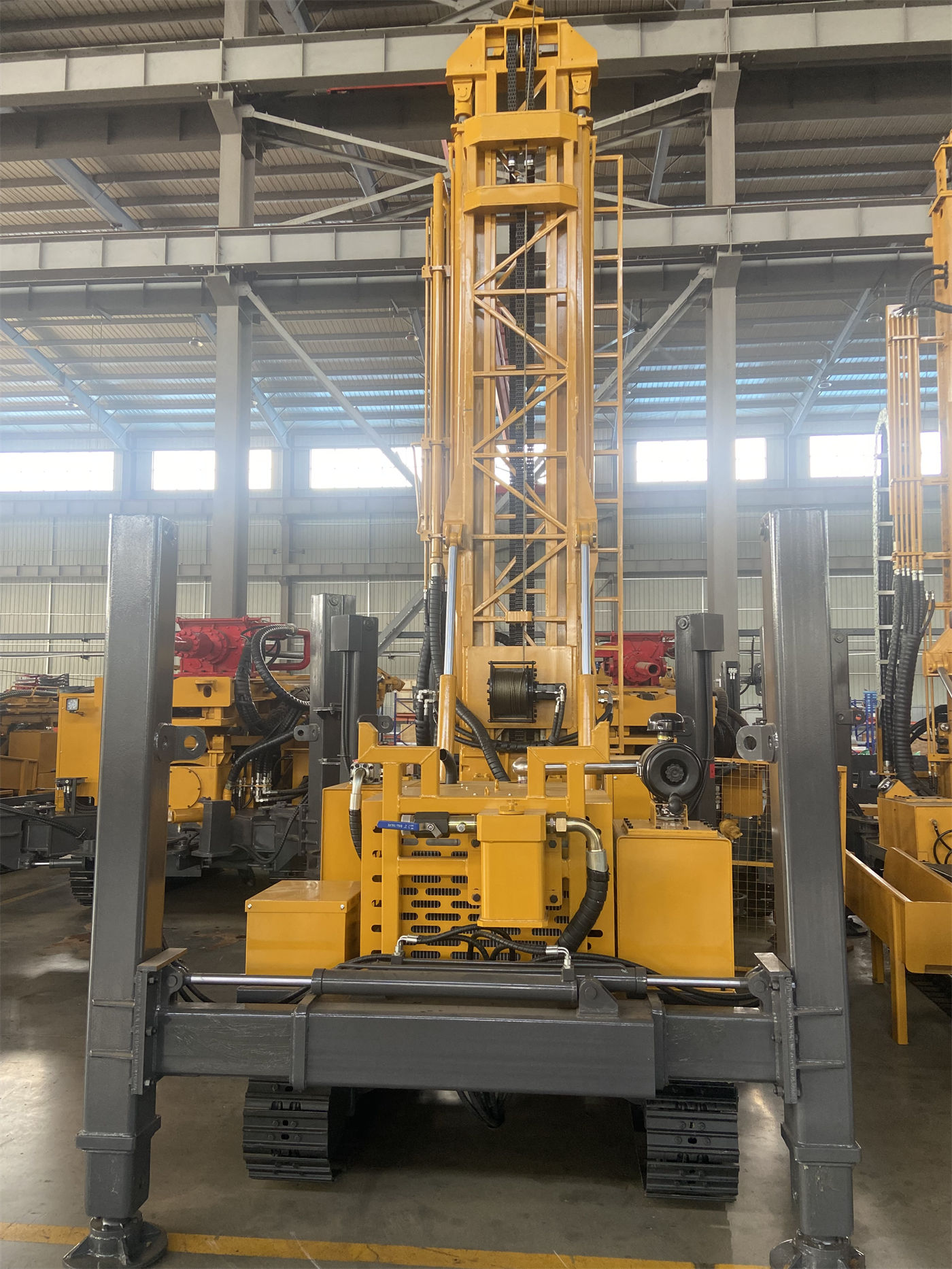
This means mast height and transfer convenience are a trade-off. In hilly village projects, limited space at borehole sites is normal, and a 1.5 m mast makes it easier to set up beside courtyard walls and fruit trees; but if a well is designed to be relatively deep, the increased number of rod connections will bring additional auxiliary time. Before the project starts, the well depth and drill pipe configuration should be calculated to determine whether this trade-off is acceptable.
Drill Pipe Diameter and Length: Affecting the Number of Transport Pieces and Manual Handling
WR180E can use 50 mm, 60 mm, and 76 mm drill pipes, with drill pipe lengths of 1.5 m and 2.0 m. The information states that shorter drill pipes facilitate manual operation, transport, and construction in narrow sites, and are more in line with the positioning of small crawler rigs.
In transfer planning, drill pipe length directly affects the number of transport pieces and the on-site handling workload. A 1.5 m drill pipe is shorter per piece, making manual carrying and loading beside village roads relatively flexible; a 2.0 m drill pipe is longer per piece and requires fewer connections, but raises requirements for transport and operating space in narrow sites. The information does not provide specific drilling efficiency for different drill pipe configurations; the actual choice should be determined based on well depth, borehole diameter, and on-site labor organization.
Power and Lifting Force: Supporting Conditions Brought by the Diesel Engine
WR180E is equipped with a 28 HP Changchai diesel engine, lifting force of 16 T, rotation speed of 40–70 rpm, and working pressure of 1.7–3.0 MPa. The information states that this power configuration is suitable for conventional shallow-to-medium water well construction, and diesel power does not depend on a fixed power grid, so it can be used for small-scale groundwater development in remote agricultural and livestock sites.
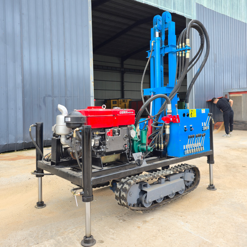
For transfers in hilly villages, the practical significance of diesel power is reduced dependence on on-site electricity; after the equipment reaches the borehole, there is no need to first solve the power connection issue. However, the information does not provide fuel consumption, continuous operating time, or power performance under special environments such as high altitude and low temperature; these must be confirmed with the manufacturer according to actual working conditions. The 16 T lifting force is used for normal drill pipe tripping and routine downhole tool handling. The information also reminds that when abnormal pulling resistance, borehole wall narrowing, or poor cuttings removal occurs, the formation and downhole conditions should be assessed first, and it is not recommended to rely solely on maximum lifting force to force handling.
Application Boundaries: Conditions That Should Be Clarified in Advance
- Drilling depth and borehole diameter: maximum drilling depth 180 m, borehole diameter 90–230 mm. Actual completed well depth should still be determined according to local groundwater level, aquifer position, borehole diameter, and construction process. If the project is mainly in complete high-hardness rock formations, or construction is long-term near the maximum drilling depth, the information recommends reassessing whether the drilling tools, power, and equipment class match.
- Formation conditions: the information mentions that soil layers, clay, sand layers, and gravel layers may experience hole collapse, narrowing, and buried drilling; drilling tools and hole stabilization methods should be selected according to formation conditions; in weathered rock and alternating soft-hard formations, parameters should be adjusted according to rock hardness and rotation load.
- Transfer transport: the information only states that it is suitable for transfer by small transport vehicles and does not provide vehicle load capacity, securing plans, or road passage conclusions. Before each transfer, inspect the crawler, mast, hydraulic lines, drill pipe connections, and power system, and secure the equipment properly during transfer transport.
- Shift organization: the rod connection frequency brought by the 1.5 m mast height needs to be considered together with well depth and borehole diameter. The information does not provide transfer time or shift efficiency data, so project duration or cost cannot be estimated from it.
Turning Transfer Planning into Pre-Start Checklist Items
When considering a small crawler water well rig such as WR180E under dispersed well site conditions in hilly villages, a practical sequence is: first group well sites by village road passage and borehole setup space, then check whether overall dimensions and weight match transport vehicles and courtyard plots, then determine drill pipe length and rod connection organization according to well depth and borehole diameter, and finally schedule diesel supply, drilling tools, and transport vehicle coordination into the borehole change sequence.
The above judgments are based on publicly available WR180E information. Actual projects still need to be verified against specific roads, sites, formations, and water supply targets. In particular, the load capacity and securing method of transport vehicles, village road slope and width, and power performance during continuous operation are not concluded in the information and should be items confirmed with the manufacturer or project owner before start of work.