












For a water supply well planned to exceed one thousand meters in depth, discovering after equipment mobilization that the air compressor displacement is insufficient, the site cannot accommodate the outriggers, or the grid capacity does not match the electric option can be very costly on deep well projects. Preparation for deep well construction does not end with towing the machine to the hole location; rather, documentation, site, power, and drilling tool compatibility must be checked in sequence before startup. Using public information about the WR1200SL as a reference, this article explains the capability correspondence of 1200 m-class ultra-deep water well equipment and the items that need to be confirmed one by one before startup. It should be noted that the following is selection and preparation thinking and does not constitute an actual construction record for any project.
Step 1: Establish the target well depth and aquifer information
The first prerequisite for deep well equipment is the target well depth, but well depth is not determined by “how deep the equipment can drill”; it is determined jointly by hydrogeological conditions and the water supply objective. The WR1200SL has a maximum drilling depth of 1200 m and a borehole diameter of 105–900 mm. This capability range covers large deep-hole projects such as deep groundwater, deep mining wells, industrial high-flow water supply, and some geothermal investigations. The public information also states that actual drilling depth still needs to be determined based on hole diameter, formation, drill pipe, air compressor, and hydrogeological conditions. Therefore, before startup, preliminary conclusions on aquifer depth, expected water volume, and water quality evaluation should be available first, and then a judgment should be made as to whether the well needs to fall within the capability range of kilometer-class equipment. If only the well depth figure is close but the aquifer is relatively shallow, the equipment does not need to be configured for maximum drilling depth.
Step 2: Determine the completed well diameter and well structure
Hole diameter is the result of completed well design, not the upper limit of equipment capability. The WR1200SL has a borehole diameter range of 105–900 mm, and the maximum hole diameter can accommodate larger well casings and higher-flow pump schemes, but the public information also notes that large-diameter construction places higher demands on the air compressor, drill bit, casing, torque, and lifting system, and it is not recommended to use the maximum hole diameter as a routine configuration over the long term. What needs to be clarified before startup is: what well casing size this well will use, how many casing strings are required, what the final hole diameter is, and whether a water-stop section and screen are needed. The wider the hole diameter is set, the more the subsequent air supply, drilling tools, and lifting load will change accordingly, so this step should be completed before equipment selection.
Step 3: Arrange the drilling process and wall protection method according to the formation combination
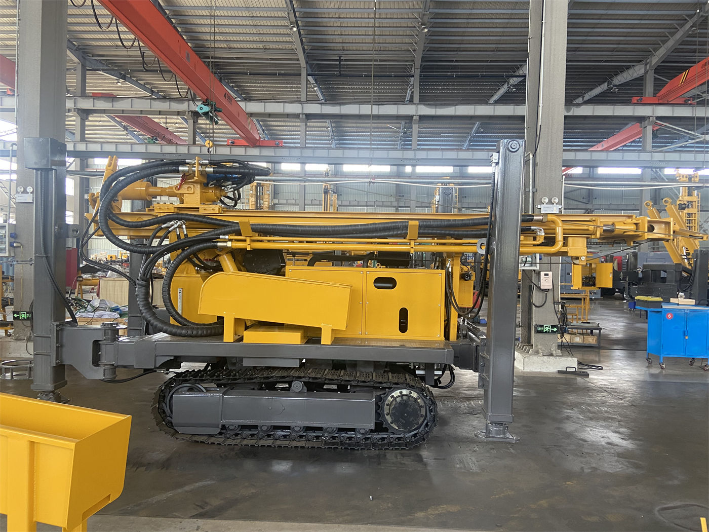
The difficulty of ultra-deep wells often lies not in the deep section but in the stability of the upper hole section. The corresponding approach given in the WR1200SL information is: for soil, clay, sand, and gravel layers, mud rotary drilling, casing, or other wall protection methods can be used; after entering relatively intact hard rock, medium- and high-pressure DTH hammer drilling can be used; when crossing faults, breccia, and fracture-developed zones, block falling, air leakage, hole shrinkage, and stuck drilling may occur, requiring reduced feed, enhanced hole cleaning, and the use of casing, foam, or other treatment methods as appropriate. Before startup, the expected formation combination should be arranged by depth, and the corresponding process and wall protection materials should be confirmed section by section, especially how much impact hole shrinkage or collapse in the upper section would have on deep drilling and tripping out.
Step 4: Confirm the power source and energy scheme
The WR1200SL uses a diesel/electric dual-power configuration, with diesel power provided by a 264 kW Cummins engine. The information states that remote mining areas, deserts, and field projects usually rely more on diesel power, while fixed drilling sites at mines, industrial parks, or long-term construction projects may have a stable power grid, so diesel and electric schemes can be configured according to site conditions. The key here is that the final power, voltage, frequency, and starting scheme of the electric part should be determined according to the project power supply system and cannot be simply converted directly from diesel power. If the electric scheme is considered before startup, the voltage, frequency, transformer capacity, cable distance, and starting current must be confirmed first; if there is no stable power supply on site, the diesel scheme is the basic configuration, and maintenance conditions for engine cooling, air filtration, fuel system, and hydraulic oil temperature must also be arranged.
Step 5: Check the air compressor and air supply compatibility
Pneumatic DTH drilling recommends a working pressure of 1.65–8 MPa and an air consumption of 16–120 m³/min. Deep holes, large diameters, and hard rock conditions place very high demands on air compressor displacement. The information clearly states that air compressor selection must consider both pressure and flow rate; if displacement is insufficient, even if the pressure meets the requirement, there may still be insufficient impact, difficult cuttings removal, and cuttings accumulation at the hole bottom. Before startup, the required air volume and pressure should be calculated according to the planned hole diameter and depth, and it should be confirmed whether an air compressor of the corresponding displacement and piping can be arranged on site. In deep holes, the return distance for rock cuttings is long, and hole bottom cleanliness is especially important. Air supply stability should be confirmed as an independent condition rather than assumed to come with the equipment by default.
Step 6: Arrange the site, outriggers, and relocation route
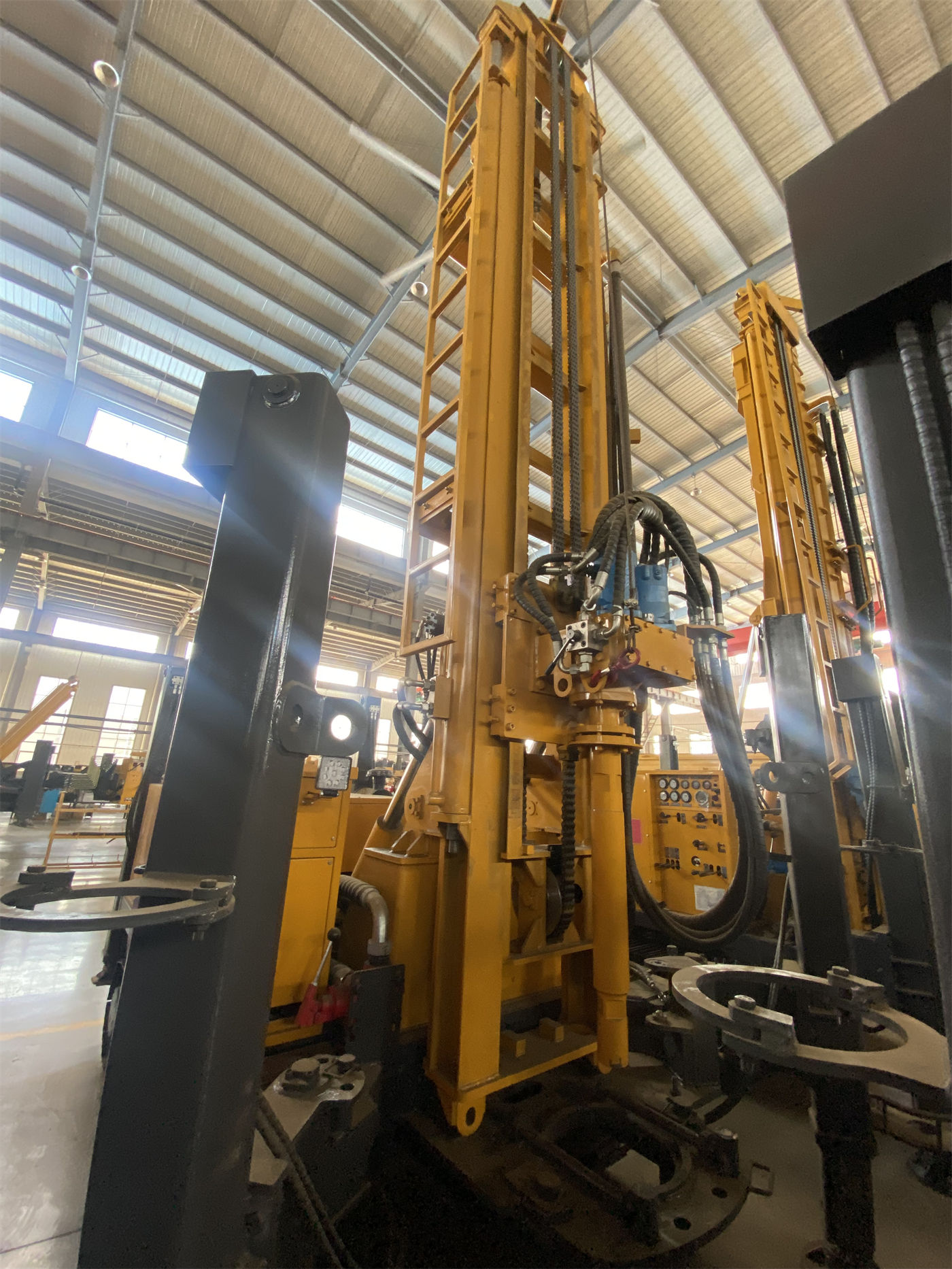
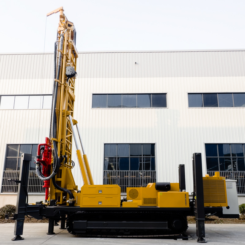
1200 m-class equipment is large in size and weight, making transport organization more complex than for small and medium drilling rigs. The WR1200SL uses a telescopic mast structure, which can shorten the transport profile during relocation and then extend to working height after reaching the hole location. The public information does not provide specific transport outer dimensions or overall weight; this part needs to be confirmed with the manufacturer and checked item by item against the width of the access road, curve radius, bridge and culvert load capacity, and internal relocation space at the site. For the site, the outrigger deployment range, drill pipe storage area, casing and mud material storage area, and placement positions for supporting equipment such as air compressors need to be confirmed. Deep well projects have long cycles, so whether the site layout leaves space for subsequent tripping and casing operations should also be considered in advance.
Step 7: Confirm whether the drill string, casing, and lifting capacity match
The WR1200SL supports 9.6 m drill pipes, with recommended drill pipe diameters of 114 / 127 mm; lifting force 60 T, axial pressure 10 T; rotary torque 30000 / 15000 N·m, corresponding to maximum speeds of 85 / 170 r/min. These values should be understood in the context of specific operations: 9.6 m long drill pipes reduce the number of connections and disconnections in ultra-deep holes and are suitable for continuous construction of deep holes above 1000 meters; the 60 T lifting force provides margin for the self-weight of the deep-hole drill string, borehole wall friction, casing weight, and downhole anomalies, but in the event of stuck drilling or hole shrinkage, the hole should still be cleaned first and downhole conditions assessed; the dual-condition torque corresponds to the different requirements of large-diameter, intact hard rock, and high-friction hole sections versus lower-resistance hole sections. Before startup, confirm the specification and quantity of drill pipes, the specification and running depth of casing, the compatibility of drill bits and DTH hammers, and whether these drilling tool combinations match the planned hole diameter and depth.
Step 8: Include materials and pump type for the well completion stage in preparation
Under deep aquifer and strong water inflow conditions, water inflow will change cuttings removal in the hole and the working conditions of the DTH hammer. During construction, the depth of the main water-producing layers should be recorded, and the air supply, hole cleaning, and casing methods should be adjusted according to the water volume. In the well completion stage, the screen, water-stop section, and final pump type also need to be designed according to aquifer thickness and water quality conditions. Although these contents are not part of the drilling rig itself, they affect hole diameter selection, casing specifications, and casing running procedures, so they should be confirmed together with the well completion design before startup rather than added after drilling is completed. The information also notes that large deep drinking water projects should complete hydrogeological surveys and water quality evaluations first, and then determine the target horizon, well diameter, and well depth.
Notes on the preparation sequence
The above sequence is not a fixed process, but there is a basic logic: well depth and aquifer, completed well diameter, and formation process determine the lower limit of equipment capability, while power, air supply, site, and drilling tool compatibility determine whether the equipment can operate as planned. The public information on the WR1200SL provides the capability range and supporting conditions of 1200 m-class equipment, but the following items still need to be confirmed in specific projects: whether the actual drilling depth can reach the design well depth depends on the combination of hole diameter, formation, drill pipe, and air compressor; the power, voltage, frequency, and starting method of the electric scheme need to be determined separately according to the project power supply system; transport outer dimensions and overall weight are not given in the information and need to be obtained from the manufacturer; the maximum hole diameter of 900 mm should not be used as a routine configuration. Checking these items one by one before startup is more controllable than making adjustments after mobilization.