












When planning a kilometer-class deep water well, a specification stating "maximum drilling depth 1000 m" only indicates where the equipment's design capability boundary lies. What really determines whether the well can be drilled as planned is whether conditions such as completion diameter, drill string load, air supply support, wall protection method, and well completion structure can all be satisfied simultaneously. Treating the maximum drilling depth as the sole basis for project feasibility is a common misunderstanding in deep water well equipment selection. Using public information on the WR1000S as a reference, this article explains where the constraints on deep-hole well completion typically lie and which conditions need to be confirmed separately before construction begins.
Several Things the Drilling Depth Number Cannot Represent
The difference between deep water wells and shallow water supply wells is not just several hundred meters of additional hole depth. As the hole gets deeper, the drill pipe's own weight increases, borehole wall friction accumulates, and the path for cuttings to return from the hole bottom to the surface becomes longer. These factors in turn affect the actual requirements for lifting force, rotary torque, and air supply displacement. At the same time, deep holes often correspond to larger completion pipe diameters and more complex screen and water shut-off section designs. Once the completion structure is fixed, the requirements for hole diameter and wall protection method will also change accordingly.
Therefore, to determine whether a rig can undertake a deep-hole project, at least the following categories of conditions must be considered together, rather than simply comparing the drilling depth number with the planned well depth.
Completion Diameter and Wellbore Structure Must Be Determined First for Equipment Capability to Have a Reference
The completion diameter of a water well is usually determined by the target water yield, well casing specifications, filter pack thickness, and water shut-off structure. The larger the diameter, the greater the rock and soil cutting volume and cuttings removal volume per unit of advance, and the higher the requirements for rotary torque, air compressor displacement, drilling tool specifications, and overall machine load. The WR1000S has a drilling diameter range of 105–800 mm, which can cover a variety of needs from conventional deep water wells to large-diameter engineering holes. However, the information also indicates that larger diameters impose higher requirements on the air compressor, drilling tools, casing, and overall machine load, and routine construction cannot be arranged based solely on the maximum diameter.
In other words, the completion diameter required by the project is an input condition, while the equipment's diameter range is only a coverable interval. What really needs to be confirmed is: what diameter is designed for this well, what size well casing will be installed, and how the screen section and water shut-off section are arranged. Then check whether the equipment still has sufficient lifting and air supply margin at this diameter.
Lifting Force and Drill String Load: The First Hurdle in Deep Holes
At kilometer-class hole depths, the drill pipe's own weight, borehole wall friction, casing weight, and local sticking all add to the load on the lifting system. The WR1000S is configured with 52 T lifting force and 8 T axial pressure, which can be used for normal tripping, deep-hole drilling tool recovery, and some large-specification casing operations. For deep-hole projects, lifting force is not just a question of "whether it can be lifted"; it determines the pace of tripping, the feasibility of running casing, and how much margin remains for handling downhole resistance.
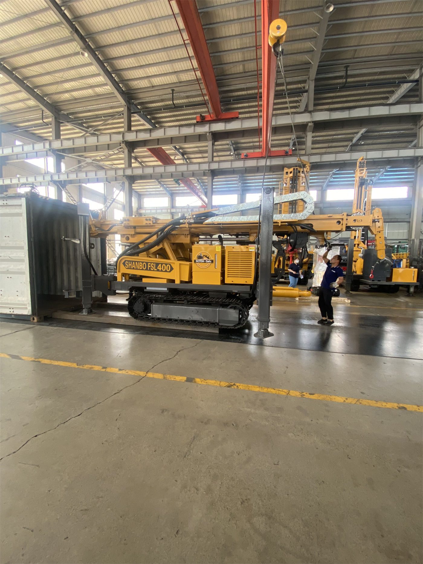
It is important to distinguish that lifting force is an equipment capability, while handling downhole anomalies still depends on hole cleaning, slow lifting, and judgment of downhole conditions. The lifting force value in the equipment information should not be understood as the ability to casually handle any stuck-pipe situation; the handling method under abnormal resistance needs to be judged by the project party based on actual downhole conditions.
Rotary Torque and Rotation Speed: Hole Diameter and Rock Properties Jointly Determine Which Range to Use
The WR1000S rotary system has a maximum torque of 26000 / 13000 N·m, corresponding to maximum rotation speeds of 70 / 140 r/min. Lower speed and high torque conditions are more suitable for large-diameter, hard rock, and high-friction hole sections; higher speeds can be used for stages with relatively lower resistance. In deep holes, the drill string is long and the load is high, so rotary parameters need to be dynamically adjusted according to drill string load and cuttings return conditions, and cannot be run at a single gear all the way to the bottom.
The significance for equipment selection is that if the project plans a large-diameter deep well and the formation is mainly hard rock, then torque reserve and stability at low speed are more informative than maximum rotation speed; if the hole sections are mainly soil, sand, and other formations with lower resistance, the utilization of speed gears will differ. The two working conditions impose different requirements on the equipment and need to be judged according to the project's formation combination.
Air Supply Support: An Often Underestimated Item in Deep-Hole Cuttings Removal
The WR1000S recommends a working air pressure of 1.6–8 MPa and an air consumption of 16–96 m³/min. In intact hard rock, it can be equipped with medium- and high-pressure DTH hammers for DTH drilling. In kilometer-class deep holes, the transport distance for bottom-hole cuttings is long, and insufficient cuttings removal can easily lead to sediment accumulation and repeated crushing, further increasing torque and energy consumption. Therefore, hard-rock deep holes have very high requirements for air compressor pressure and displacement. Actual selection must be comprehensively determined based on DTH hammer model, hole diameter, hole depth, altitude, and rock hardness; insufficient displacement will directly affect impact and cuttings removal efficiency.
It should be clarified here that the equipment information gives recommended working pressure and air consumption ranges, which does not mean any air compressor configuration can satisfy all combinations of hole depth and diameter. Air compressor selection is a supporting link in deep-hole projects that requires separate calculation and cannot be based solely on the drilling rig's own parameters.
Wall Protection and Process Switching: From Overburden to Aquifer, Arrange by Sections
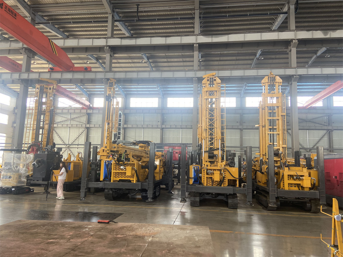
Deep water wells rarely use a single process all the way to the bottom. The WR1000S supports mud rotary drilling, which can be used for upper hole sections such as soil, clay, sand, and gravel layers. The stability of the upper hole section directly affects subsequent deep-hole construction. Mud, casing, and other wall protection methods can be used to first establish a stable hole section, then switch to the DTH hammer process when entering rock formations.
When a deep hole passes through a fault fracture zone, block falling, hole shrinkage, air leakage, and sticking may occur. The information indicates that after entering such hole sections, excessively fast advancement should be reduced, hole cleaning should be strengthened, and casing, foam, or other hole stabilization measures should be used as appropriate. In case of severe air leakage, the scale of fractures and cavities should be analyzed rather than relying solely on increasing air compressor pressure. After entering the main deep aquifer, water inflow will change the cuttings removal and pressure state in the hole. The depth of the main water-producing layers should be recorded, and the air supply, hole cleaning, and casing plans should be adjusted accordingly.
These process arrangements impose sectional requirements on the equipment: the upper overburden requires a mud system and wall protection support; the lower hard rock requires a DTH hammer and sufficient air volume and pressure; and the aquifer section imposes additional requirements on hole cleaning and completion structure. Equipment capability is only one part of this; the process plan and supporting materials need to be implemented simultaneously.
Drill Pipe and Mast: Auxiliary Rhythm Determining Continuous Deep-Hole Construction
The WR1000S adopts a telescopic mast structure, supports 6 m drill pipes, and recommends a drill pipe diameter of 114 mm. For kilometer-class drilling, if too short drill pipes are used, the number of connections and disconnections will increase significantly, and auxiliary time and labor intensity will rapidly accumulate. 6 m drill pipes can reduce the number of connections and are more suitable for long-cycle deep-hole construction. The information also indicates that drill pipe threads, straightness, and fatigue condition should be included in continuous inspection.
The role of the telescopic mast is to balance the overall machine profile in transport condition and the working height required in operating condition, which has practical significance for the relocation and site layout of large deep-hole equipment. The equipment's fast lifting speed of 30 m/min and fast advancement speed of 61 m/min are mainly used for power head return, drill pipe handling, and auxiliary actions. In deep-hole construction, a single auxiliary operation may seem short, but long-term accumulation will affect the total project duration.
Power, Travel, and Site Conditions: Supporting Constraints Beyond the Equipment
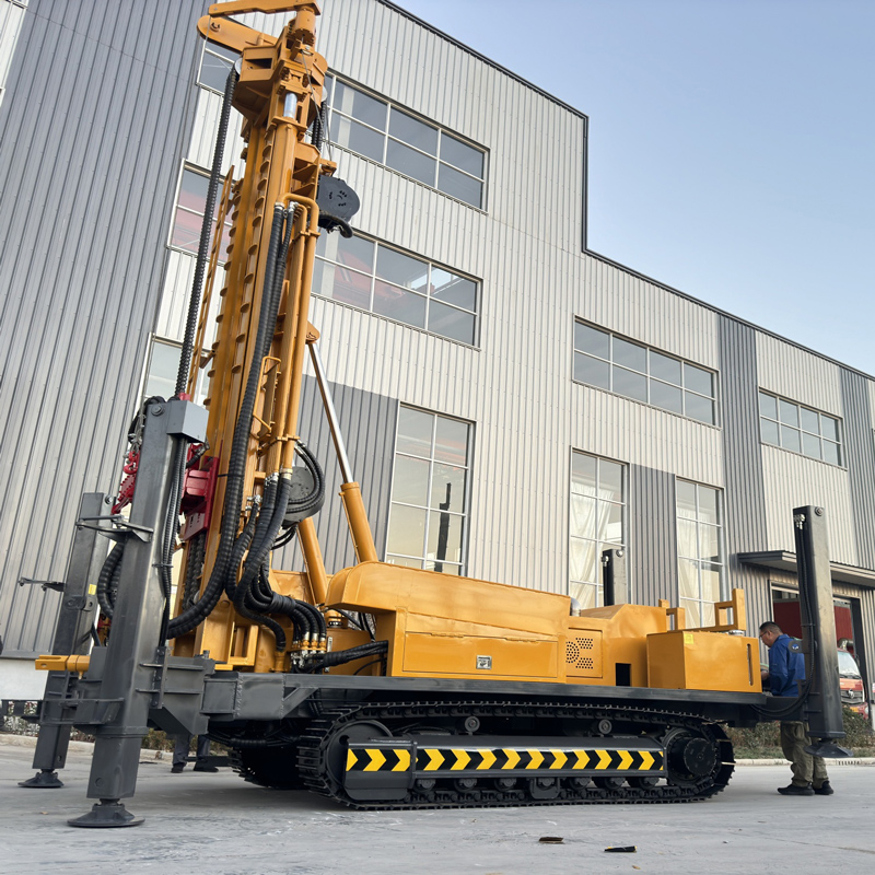
The WR1000S is equipped with 194 kW diesel power, has an overall weight of approximately 17.8 T, dimensions of approximately 7.3 × 2.25 × 2.75 m, travel speed of approximately 5 km/h, maximum climbing angle reference of 21°, hydraulic outrigger stroke of 1.7 m, and auxiliary winch lifting force of 2.5 T. These data do not correspond to drilling capability itself, but to equipment entry, positioning, and site organization conditions.
- Before transport, confirm the flatbed truck load capacity, road width and height limits, and bridge load capacity. The telescopic mast must be reliably locked, and 6 m drill pipes and casing should be secured separately.
- Equipment travel speed is mainly used for relocation within the site and between hole positions. Before moving, confirm road load capacity, slope, turning radius, and soft ground conditions.
- Hydraulic outriggers can help level and stabilize the equipment on uneven platforms. On soft ground, use mats with sufficient area to prevent long-term settlement.
- The auxiliary winch can be used for handling DTH hammers, drill pipes, casing tools, and other site accessories. Ultra-deep hole projects have more and heavier supporting drilling tools, so lifting routes and material storage areas need to be reasonably planned.
These conditions do not directly determine well completion quality, but if any one of them is not implemented, the equipment may arrive at the site but be unable to start work as planned.
Which Conditions Still Need to Be Confirmed Based on Project Data
The above content explains the capability range and applicable conditions corresponding to the public information on the WR1000S, not a selection conclusion for any specific project. Actual well depth still needs to be determined based on hydrogeological data, formation structure, and target aquifer. Before comparing equipment for a deep water well project, at least the following information needs to be confirmed:
- Target well depth and burial depth of the main aquifer;
- Completion diameter, well casing specifications, and design of screen and water shut-off sections;
- Formation combination, including upper overburden thickness, hard rock type, and distribution of fracture zones;
- Air compressor configuration plan and on-site air supply conditions;
- Wall protection materials, casing specifications, and supply of well completion materials;
- Access roads, transport vehicles, and hole position site conditions.
If any one of these conditions is not yet clear, equipment selection can only provide a conditional judgment and cannot directly conclude that a certain model is definitely suitable. The constraints on deep-hole well completion are never just the single number of maximum drilling depth. Only by clearly matching diameter, load, air supply, wall protection, and completion structure item by item can equipment capability have a comparable basis.