












Slope anchoring holes, retaining wall anchor cable holes, and equipment foundation pre-drilling holes often have depths within tens of meters, so the footage alone is not a large project. What truly complicates equipment selection is the drilling location itself: on slopes, the drilling attitude must be adjusted according to the design hole direction; within scaffolding or enclosures, machine width must be controlled; and on already paved sites, there is a desire to avoid damaging the ground. When these three constraints appear simultaneously, a rig with large drilling depth and high tonnage may not be the appropriate starting point.
Using the published information on the DTH30C as a guide, the following breaks down the work objectives in order: which requirements should be defined first, which capabilities correspond to them, which figures cannot be directly taken as conclusions, and which conditions must await confirmation from formal technical documentation.
First Distinguish Two Types of Holes: Anchoring Holes Need Attitude, Pre-Drilled Holes Need Positioning
Although slope anchoring and foundation pre-drilling both fall within the shallow-to-medium hole range, the starting point of the work sequence differs.
For anchor bolt holes, anchor cable holes, and drainage holes on slopes, the hole direction is determined by design and may be vertical, inclined, or locally near-horizontal. After the equipment enters the slope, the first task is to adjust the power head to the design angle, and the second is to maintain stability in that attitude. The hole depth is not large, but if the angle cannot be set correctly, the cost of re-drilling or modifying holes later is higher than the drilling itself.
Foundation pre-drilling appears more often in equipment foundations, guardrail piles, short piles, and hard rock foundations. Hole positions are usually arranged along an axis or according to pile locations, and the equipment must repeatedly reposition between nearby holes. Machine width, turning radius, and the degree of ground damage directly affect the number of repositioning moves and the workload of site restoration.
Looking at these two types of needs together, they point to the same set of equipment characteristics: drilling depth need not be very deep, but attitude must be adjustable; the machine body must be compact, but the undercarriage must be able to travel on crushed stone, compacted soil, and construction access roads.
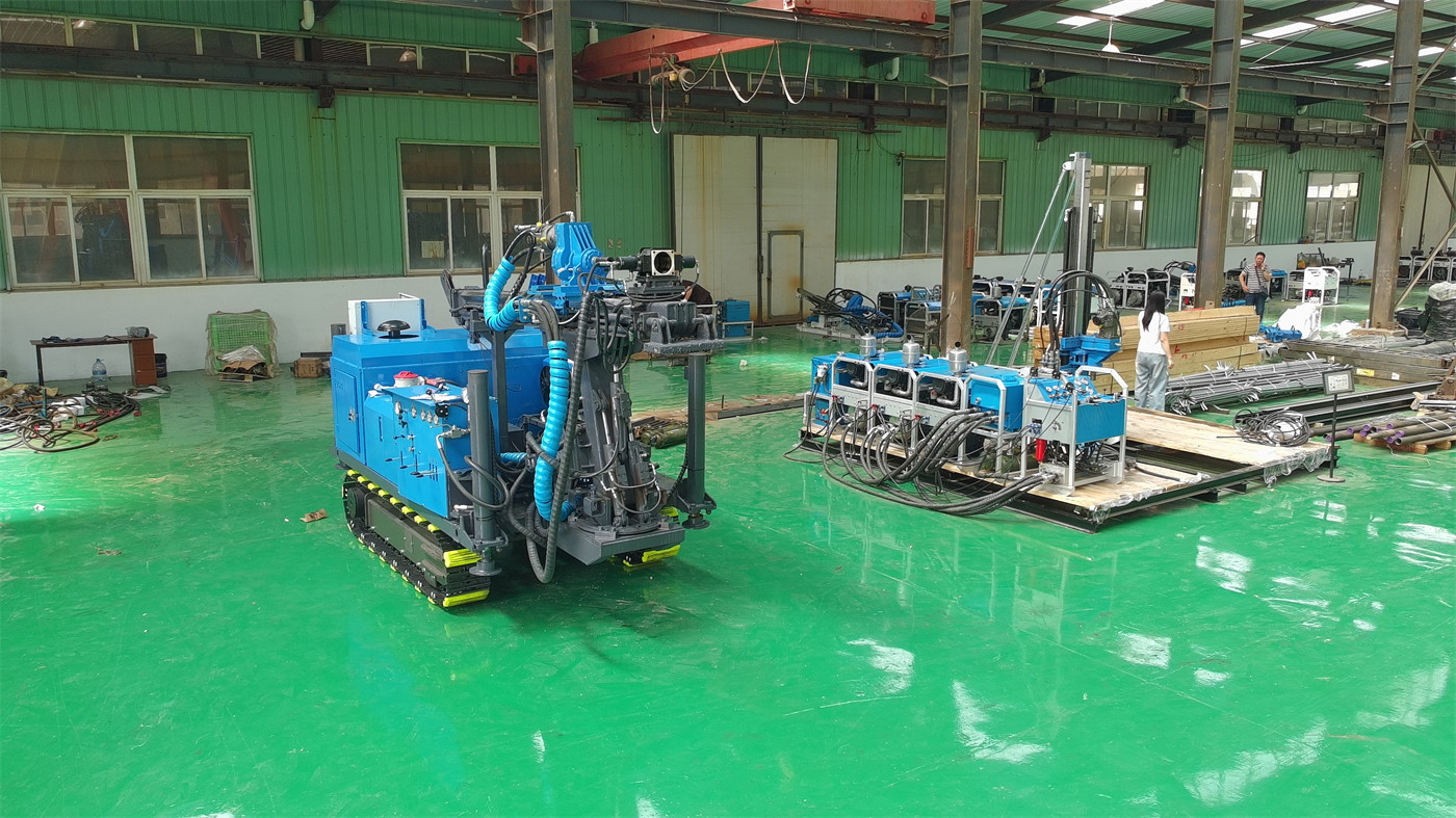
Parts of the DTH30C Specifications That Match the Needs
Drilling Depth and Hole Diameter: First Confirm Which Range the Target Hole Depth Falls Into
The published maximum drilling depth is 30 m, with a hole diameter of 76–280 mm. This range covers engineering short holes and shallow-to-medium holes, not deep water wells or deep exploration holes. If the project also includes water supply wells deeper than 200 m, this equipment cannot serve as the solution for such holes; the documentation itself clearly states that deep wells should use dedicated water well drilling rigs.
The wide hole diameter range means the same machine can switch between small diameters for anchor bolt holes and larger diameters for foundation pre-drilling. However, the upper diameter limit corresponds to the equipment's capability boundary. The actual diameter selected also depends on whether the design hole diameter, DTH hammer specifications, and air compressor output can be matched.
Swing Angle and Tilt Adjustment: Corresponding to Attitude Adjustment on Slopes
The documentation states that the equipment has an 18–180° swing angle and tilt adjustment function. For slope anchoring, this is one of the prerequisites for constructing according to the design hole direction. It should be noted that the original documentation only states 'equipped with tilt adjustment function' and does not provide a specific angle range. For anchor cable holes or drainage holes requiring specific tilt angles, the final production configuration and technical confirmation documents should prevail; the tilt range cannot be directly inferred from the swing angle range.
3500 N·m Torque and Medium-High Hardness Rock
The maximum rotary torque is 3500 N·m, applicable to rock hardness of approximately f = 8–24. The documentation lists medium-high hardness rocks such as limestone, granite, sandstone, and basalt. In DTH drilling, rotary torque is mainly used to overcome friction between the drilling tools and the hole wall and to drive the bit rotation; impact is provided by the DTH hammer, and the two must match. Whether the torque is sufficient cannot be judged by this figure alone; hole diameter, bit wear, and cuttings return conditions must also be considered.
The documentation also states that if rotary resistance continues to increase, cuttings return decreases, or the bit jumps noticeably, parameters should be adjusted and the hole cleaned. These are judgment conditions during construction, not results automatically guaranteed by the equipment.
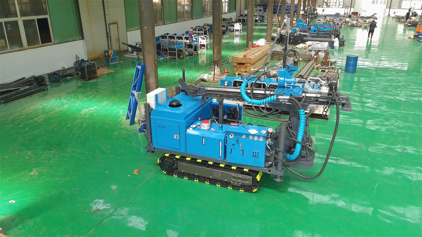
Machine Width and Overall Weight: Corresponding to Restricted Sites and Paved Surfaces
The overall dimensions are approximately 3200 × 1200 × 1850 mm, with a width of about 1.2 m and an overall weight of about 2500 kg. For plant areas, enclosed construction sites, and narrow construction passages, this width is a prerequisite for entry and deployment. The documentation also explicitly requires confirming turning space, ground bearing capacity, underground pipelines, and surrounding buildings before entering the construction point.
The rubber crawler undercarriage is described in the documentation as more friendly to finished paved surfaces and concrete floors, while also providing traction advantages on crushed stone, compacted soil, and generally uneven sites. This is a statement of the applicable conditions for the undercarriage type, not a claim that the equipment can travel on any ground without treatment.
Slide Frame Stroke and Feed Speed: Distinguish Each Action
The slide frame stroke is 3.2 m, effective stroke 2.2 m, piling height 2.2 m, and feed speed 53 m/min. The documentation explains 53 m/min as the rapid movement speed of the feed mechanism, used for power head return, drill pipe handling, and non-drilling actions; it cannot be understood as the actual penetration rate in rock. Actual penetration is affected by rock hardness, hole diameter, DTH hammer specifications, air compressor capacity, and bit wear.
The 2.2 m effective stroke corresponds to medium-short drill pipes and short pile construction. For hole depths within 30 m and arrangements with relatively short single drill pipes, the number of pipe connections will be greater than with long-stroke equipment; this auxiliary time must be calculated separately during continuous multi-hole operations.
If Supporting Conditions Are Not in Place, Equipment Capabilities Cannot Be Realized
DTH drilling relies on compressed air to drive the DTH hammer and discharge cuttings. The reference air consumption given in the documentation is approximately 8 m³/min, while noting that the original table actually marked 8 m²/min, which is interpreted as m³/min according to the common unit for compressed air flow; the formal technical documentation shall prevail. This unit issue must be confirmed before use because it directly affects air compressor selection.
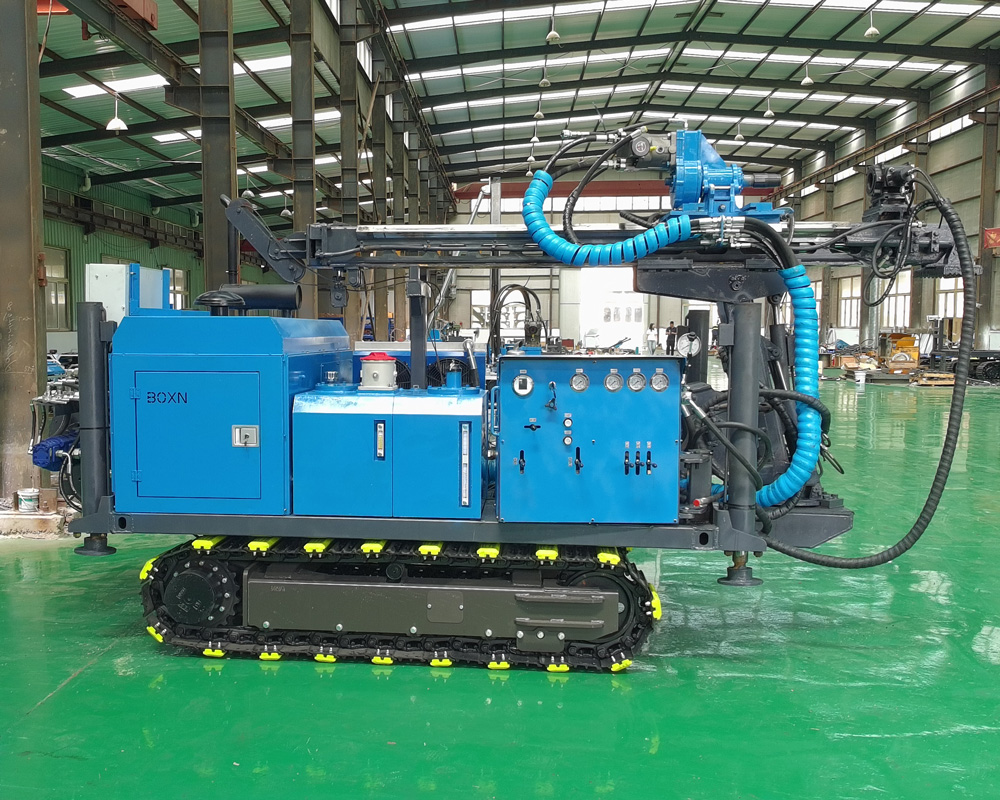
In addition, the common supporting items listed in the documentation include DTH hammers, bits, drill pipes, casing tools, air compressors, high-pressure air hoses, oil mist lubricators, dust collectors, or water mist dust suppression devices. Dust is significant when drilling dry hard rock; whether to equip a dust collector or water mist dust suppression should be decided based on local construction regulations and site conditions.
For short piles or specific foundation pre-drilling, corresponding piling or pre-drilling attachments can also be selected according to the project. Such attachments are supporting conditions of the overall machine solution, and interfaces and load-bearing capacity must be confirmed separately during selection.
Conditions That Push This Equipment Beyond Its Boundaries
- Hole depth exceeding 30 m: already beyond the maximum drilling depth specified in the documentation.
- Deep water wells or deep exploration: the documentation explicitly states these are outside the equipment's scope of application.
- Hole diameter exceeding 280 mm: beyond the upper limit of drilling diameter specified in the documentation.
- Low-hardness soft soil or thick overburden: DTH drilling is mainly for hard rock; loose layers and soil-rock mixed layers require reduced feed speed and, depending on conditions, casing or starting drilling tools. The documentation does not list such formations as primary construction targets.
- Design holes requiring a precise tilt angle range: the original documentation does not provide tilt angle values; configuration must be confirmed first.
- Insufficient site bearing capacity or unstable slopes: the documentation requires checking platform stability and rockfall risk before starting work; direct operation on unstable slopes is not permitted.
These boundaries do not negate the equipment; they indicate which segment of the problem it solves. Placing a 30-meter-class engineering DTH rig into deep well or large-diameter pile foundation projects results in a mismatch in both capability and supporting equipment.
Items to Verify in Sequence
If a project involves both slope anchoring and foundation pre-drilling, proceed in the following order rather than comparing machine models first:
- First define the design hole depth, hole diameter, and hole direction for each type of hole, and confirm whether all fall within 30 m and 76–280 mm, and whether tilt angles are within a confirmable range.
- Next, review the distribution of hole positions: whether slope holes require multiple attitude adjustments, whether foundation holes require frequent machine repositioning, and whether site width and ground conditions allow a 1.2 m wide machine to enter and turn.
- Then verify air supply: select the air compressor according to the confirmed air consumption unit, and confirm the length and site layout of high-pressure air hoses.
- Finally, confirm drilling tools and attachments: whether DTH hammers, bits, drill pipes, casing tools, and possibly piling or pre-drilling attachments match the final configuration.
The documentation does not provide penetration efficiency, hole quality, or cost data from actual projects, and this article does not infer them. Whether the equipment merits consideration depends on whether the above conditions can be satisfied simultaneously; if they cannot, the process should be adjusted or a different equipment class selected, rather than taking maximum parameter values.