












When you open the documentation for an underground core drill, the angle and drilling depth are often laid out on two rows: one row is the borehole direction, and the other is the reference drilling depth for each size. At first glance they look like two independent sets of parameters, but in actual use they constrain each other—for the same NQ size, the 90° direction lists 800 m, the 0° direction lists 400 m, and the -90° direction lists only 200 m. If the two rows are not read together, it is easy to mistake the maximum drilling depth in one direction for the capability of the whole machine, or to select equipment based on the planned hole depth only to find that the planned borehole direction is not in that tier at all.
The actual relationship between the two rows: angle is the tier switch, and drilling depth is the value under that tier
In the publicly available CR800UG data, drilling depth is not a single value but is given in groups by borehole direction:
| Borehole direction (reference) | BQ | NQ | HQ |
|---|---|---|---|
| 90° | 920 m | 800 m | 380 m |
| 0° | 600 m | 400 m | 200 m |
| -90° | 350 m | 200 m | 150 m |
This set of data shows that drilling depth varies with borehole direction rather than being a fixed upper limit. If you only remember "NQ 800 meters" when reading the documentation, you will miss the declining capability for horizontal holes and upward holes. Conversely, if you only see the 400 m for the 0° direction, you may underestimate the capability for downward holes. The two rows must correspond as a set to be meaningful for selection.
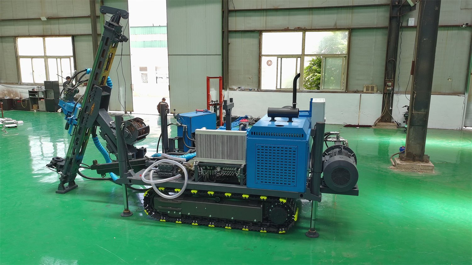
Why angle affects drilling depth: the drill string is subjected to forces in different directions
In the documentation, 90°, 0°, and -90° correspond to the downward, horizontal, and upward directions, respectively. In these three directions, the self-weight of the drill string acts differently on feed and hoisting: in a downward hole, the self-weight of the drill string helps advance the bit, but a greater weight must be overcome when tripping in and out; in a horizontal hole, the drill string rests against the wall, and friction increases with hole depth; in an upward hole, the self-weight of the drill string opposes the advancing direction, and the conditions for returning cuttings in the hole are also more complex. These differences are reflected in equipment capability as different reference drilling depths for the same size in different directions. The documentation does not elaborate on the specific force calculations, but the drilling depth gradient across the three directions itself shows that angle is not an additional note but a limiting condition on the drilling depth data.
Look for the corresponding row according to the direction the project intends to drill
Suppose a mine plans to verify the downward extension of an orebody from an existing roadway, with a designed hole depth of 700 m and NQ size; then the 90° row should be checked: the NQ reference drilling depth is 800 m, leaving some margin. If the same project is changed to drill a horizontal hole from a crosscut toward the side to trace the orebody boundary, and the hole depth is still designed at 700 m, the 0° row gives only 400 m for NQ, so the equipment capability does not cover it. What should be done at this point is not to upsize the equipment but to recheck the borehole design: whether staged drilling can be adopted, whether a horizontal hole is necessary, or whether the size should be adjusted. The three directions given in the documentation are reference conditions, and the definition of the positive and negative signs of angle may differ from mine to mine; before formal construction, the on-site installation direction and design drawings should be taken as the basis.
Correspondence between drilling depth tiers and other parameters
Angle and drilling depth determine the capability boundary. Whether the equipment can work stably within this boundary also depends on whether the supporting parameters match.
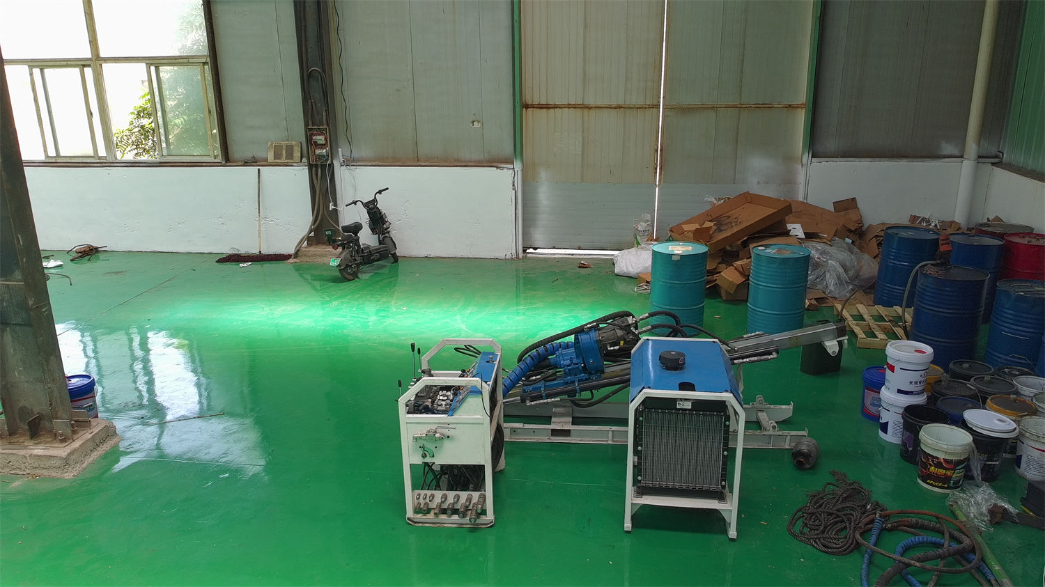
Feed and hoisting
The CR800UG feed mechanism is driven by a hydraulic cylinder, with a stroke of 1800 mm, a thrust of 65 kN, and a pull force of 130 kN. The documentation specifically notes that the stress states of the drill string in horizontal, downward, and upward holes are not the same, and that feed and pullback parameters should be adjusted according to borehole direction, hole depth, and changes in friction. This and the tiering of drilling depth by direction are two sides of the same thing: when the angle changes, not only does the drilling depth value change, but the operating parameters must also be adjusted accordingly.
Winch rope capacity
The wireline winch has a rope capacity of 800 m and uses 6 mm steel wire rope. This value corresponds to the NQ drilling depth of 800 m in the 90° direction. If the project plans to drill 400 m in a horizontal hole, the rope capacity has a surplus; but if a horizontal hole is mistakenly designed for 800 m, the rope capacity itself will become a hard constraint. When reading the documentation, the winch rope capacity should be checked together with the drilling depth table rather than remembered separately as "800 meters."
Power head speed and torque
The power head is a hydraulic top drive, with a speed of 0–1500 rpm, a torque range of 600–1480 N·m, and a 107 variable motor. The documentation states that the relatively wide speed range makes it convenient to select the working state according to BQ, NQ, and HQ sizes and rock hardness. It does not give recommended speeds for each size, so it can only be judged that the equipment has adjustment room; the actual drilling efficiency of a given size in a given direction cannot be inferred from this.
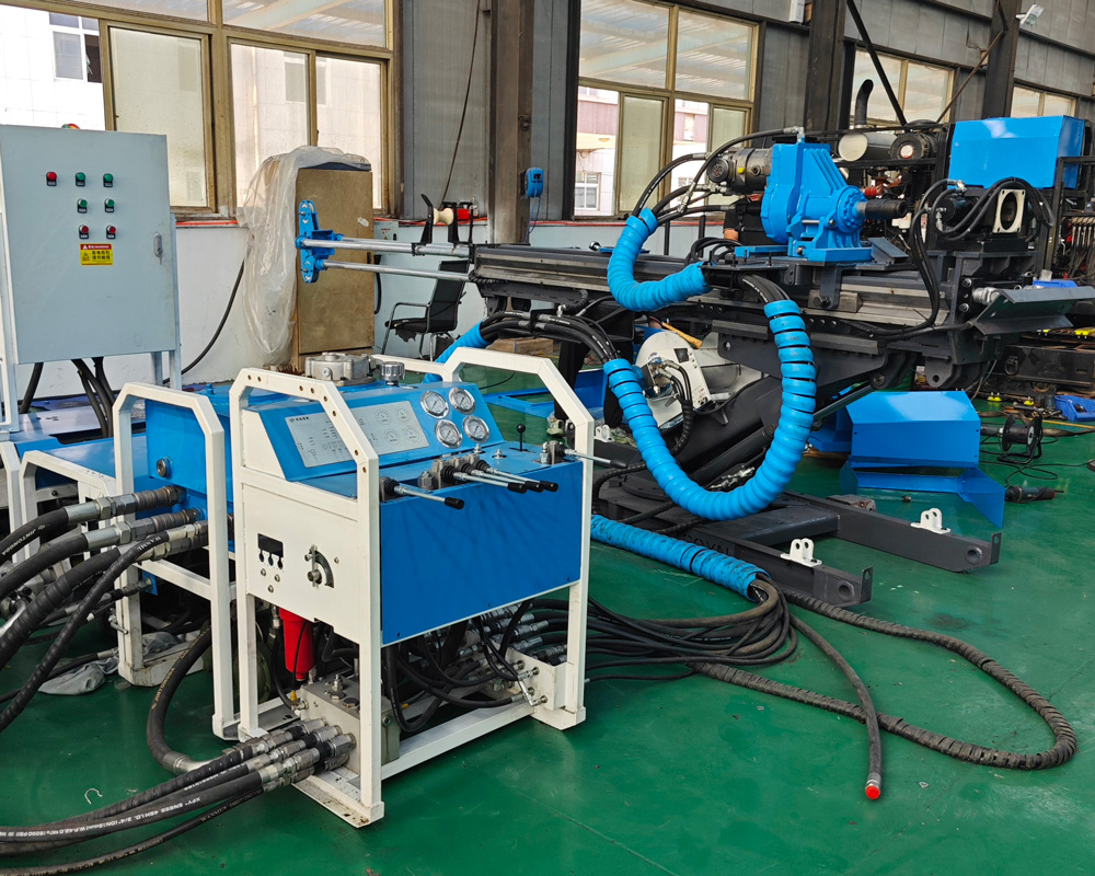
Several preconditions that are easy to miss when reading the documentation
- Definition of borehole direction: the documentation groups by 90°, 0°, and -90°, but different mines may define the positive and negative signs differently, so the on-site installation direction and design drawings should be taken as the basis.
- Electrical configuration: the power system is 22 kW × 3 or 30 kW × 2 motors, and the documentation clearly states that the standard motor configuration cannot be directly regarded as an explosion-proof configuration; areas with explosion-proof requirements must be separately confirmed in accordance with local regulations.
- Transport and assembly: modular split transport, with the power station at 240/270 kg, the feed mechanism at 130 kg, the base frame at 120 kg, the oil tank unit at 120 kg, and the operating unit at 90 kg (the documentation also has a 130 kg marking for the operating unit; the formal technical confirmation documentation should prevail).
- Flushing and circulation: an optional 120 series high-pressure plunger pump, with a maximum flow of 120 L/min and a maximum pressure of 70 bar, for flushing and some special circulation conditions.
Items that still need to be confirmed with the manufacturer
The publicly available documentation gives drilling depth values under reference conditions. The following items still need to be confirmed before formal selection: whether there are corresponding drilling depth references for intermediate angles outside the three directions (for example, around 45°); the influence of the actual downhole tool assembly, flushing fluid type, and rock formation conditions on drilling depth; which of the two markings for the weight of the operating unit should prevail; and the electrical scheme under the specific mine voltage, frequency, cable length, and starting method. These contents are not elaborated in the documentation and cannot be inferred on your own.
Returning to the matter of reading the documentation itself: the angle and drilling depth rows are not a parallel parameter list but a set of corresponding relationships. First determine the project's planned borehole direction, then look up the size and drilling depth under that direction, and then check item by item against feed, hoisting, and winch rope capacity to judge whether the equipment capability covers the work target. Any conclusion drawn from a single drilling depth figure alone lacks the other half of the basis.