












After a mining area has completed surface mapping and shallow hole reconnaissance, the next step is often to drill a batch of medium-depth core holes: hole depths ranging from a few hundred meters to around eight hundred meters, hole locations scattered across several ore blocks, exploration line directions requiring many holes to be drilled at an angle, and formations interbedded with fractured zones and water-bearing fissures. At this point, the contractor will ask: can one integrated core drill rig cover this, or must it be organized as portable modular equipment plus auxiliary shifts? This question cannot be answered by looking at the drilling depth column alone; coring specifications, relocation methods, inclined hole angles, and in-hole handling capabilities must be compared in the same table.
First, define what "sufficient" means in this type of mining area
The goal of coring tasks in medium-depth mining areas is usually not to pursue the maximum depth of a single hole, but to steadily obtain continuous cores usable for logging and assay within one exploration cycle. From this, several verifiable conditions can be derived:
- The target hole depth and coring diameter must fall within the equipment's reference drilling depth range, with margin left for in-hole friction and changes in hole wall conditions;
- Hole locations are scattered, and the equipment needs to be repeatedly moved short distances within the mining area; fewer procedures for site entry and re-positioning are more conducive to continuity;
- Orebody attitude determines that some boreholes need to be inclined; the equipment must have corresponding angle adjustment capability, and the site must also be able to level the ground and secure the machine body;
- Boreholes must continuously pass through overburden, host rock, alteration zones, and mineralized sections; the equipment must be able to switch between rotational speed and torque working states across different lithologies;
- In deep hole sections, the drill string weight, hole wall friction, and local diameter reduction accumulate; lifting capacity must leave room for handling, but operationally, increasing lifting force cannot be treated as the only means to resolve sticking.
If any one of these five items does not match, the answer to "is integrated sufficient" may change. Below, the public CR800I data are compared item by item.
Drilling depth specifications and coring diameter: first see which tier the planned hole depth falls into
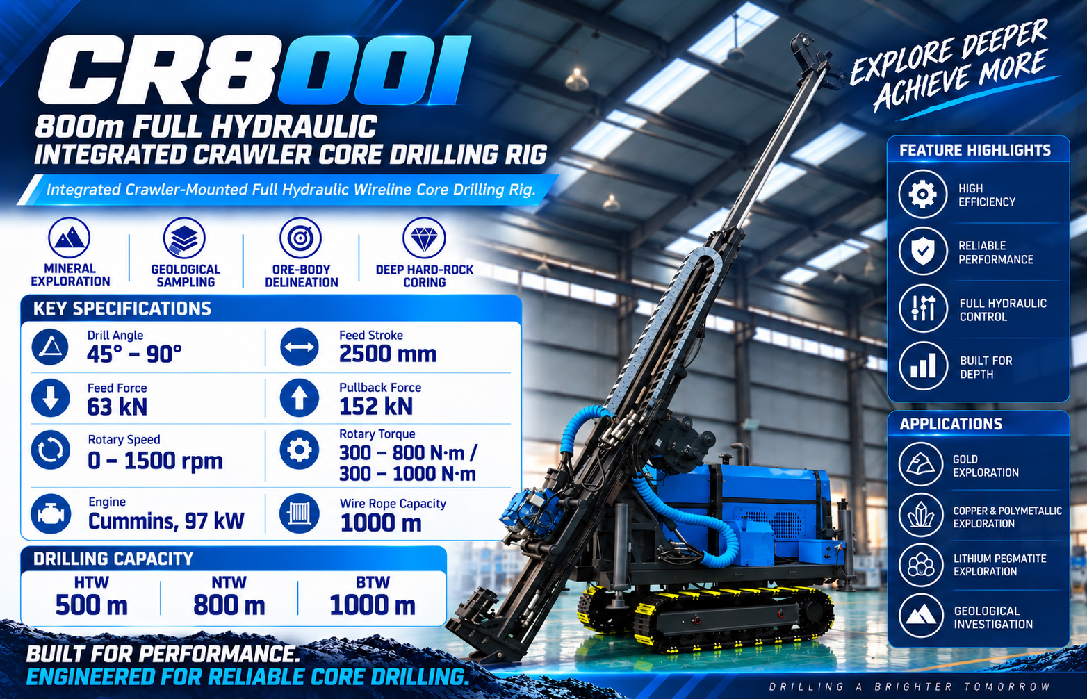
The CR800I is positioned at a reference drilling depth of 800 m for NTW size; in the same data, the HTW reference drilling depth is 500 m and the BTW reference drilling depth is 1000 m. These three figures correspond to reference capabilities under different coring diameters, not drilling depth limits that can be freely interchanged under the same diameter. For medium-depth mining areas, if the main task is orebody tracking and infill control using NTW or a similar diameter, the 800 m tier is relatively close to the depth targets of most holes; if the project requires continuous coring at a larger diameter, the reference drilling depth will be correspondingly shorter, and the hole depth arrangement must be rechecked against the HTW tier.
Conversely, if planned hole depths are generally within five to six hundred meters, this rig will leave some margin in the NTW tier, but margin does not equal efficiency improvement; the actual drilling pace still depends on formation, bit matching, and mud circulation. The data do not provide specific penetration rates for each diameter, and such judgments can only be confirmed based on site conditions.
The integrated layout corresponds to relocation and positioning
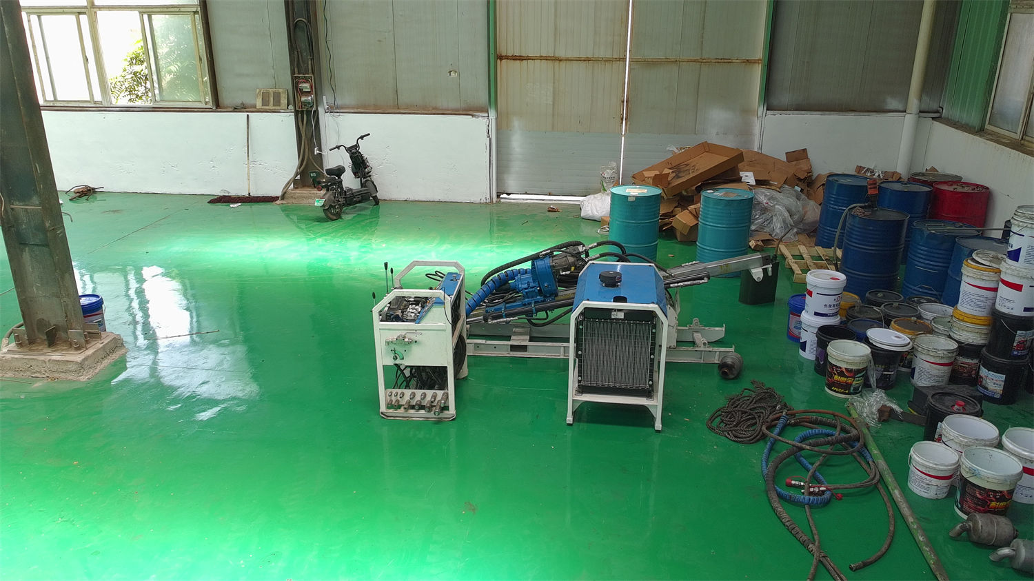
In this type of mining area, hole locations are often not on the same platform. The CR800I concentrates power, hydraulics, mast, power head, winch, and mud circulation on the same crawler chassis, so the main modules do not need to be assembled piece by piece on site. The data give a crawler travel speed of approximately 2.5 km/h, a reference gradeability of 30°, overall transport dimensions of approximately 5000 × 1800 × 2550 mm, and a weight of approximately 5800 kg.
What this set of data shows is that it is suitable for short-distance repositioning between gravel roads, mountain exploration platforms, and temporary construction access roads in the mining area; during transport, road width and turning conditions should be checked against the overall dimensions. But it does not eliminate transport issues—a transport length on the order of 5000 mm and a weight of 5800 kg still require prior verification of road load-bearing capacity, curve radius, and loading/unloading conditions. If the holes are separated by forest roads or narrow bridges that require disassembly to pass, the integrated structure instead becomes a constraint; in that case, a modular solution should be considered rather than forcing this rig through.
45°–90° drilling angle and inclined hole layout
In quartz vein-type gold deposits, shear zone-type gold deposits, and structurally altered deposits, orebodies often have inclined extensions and local pinch-out and reappearance. The CR800I supports a drilling angle of 45°–90°, the mast is a ground-contact integrated structure, and the feed stroke is 2500 mm. During inclined hole construction, this angle range allows boreholes to pass through mineralized zones along the exploration line direction, rather than being limited to near-vertical holes.
It should be made clear that angle capability is only an equipment condition. The data also indicate that for inclined hole construction, site leveling and machine body securing should be completed in advance to avoid platform settlement affecting hole deviation control. In other words, whether the 45°–90° range can actually be used at a given hole location also depends on whether the platform is level, whether the foundation is stable, and whether the drill string assembly matches the designed hole deviation. These are on-site organizational matters; the data do not provide specific hole deviation control accuracy, and it is not appropriate to promise a certain hole deviation range based on them.
Rotational speed and torque selection during continuous cross-layer coring
In copper, lead-zinc, and polymetallic deposit exploration, a single hole often must continuously pass through overburden, host rock, alteration zones, fractured zones, and mineralized sections. The CR800I power head has a rotational speed range of 0–1500 rpm, high-speed gear torque of approximately 300–800 N·m, torque gear of approximately 300–1000 N·m, high-speed gear transmission ratio of 1:2.2, and low-speed gear of 1:3.
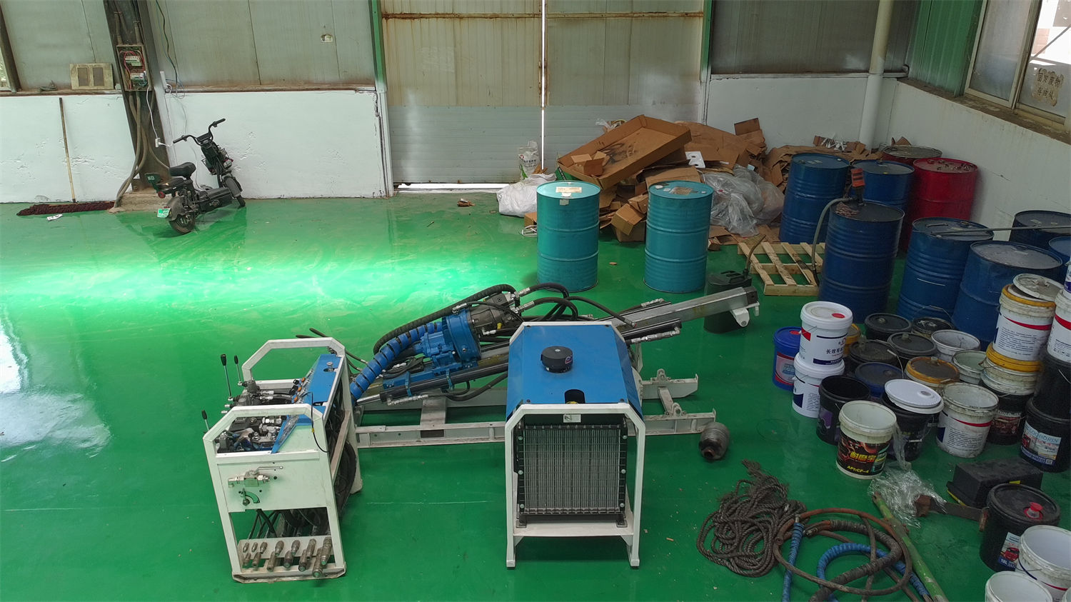
This set of data corresponds to two working orientations: intact hard rock formations place more emphasis on stable rotational speed and bit matching, while fractured or higher-resistance hole sections require appropriately lower rotational speed and a higher proportion of torque work. During selection, the questions to ask are: which category the main lithology of the mining area falls into, and what proportion of the borehole passes through fractured zones. If the entire hole is mainly intact hard rock, the high-speed gear rotational speed range is more meaningful; if alteration zones and fractured zones account for a large proportion, the torque gear will be used more frequently, and the requirements on the hydraulic system and operator judgment will also change accordingly. The data do not provide recommended parameters for each gear under different lithologies; this part must be determined through on-site trial drilling and bit manufacturer recommendations.
Lifting capacity and boundaries as hole depth increases
The CR800I provides 152 kN pull-up force and 63 kN feed force; the winch uses 6 mm wire rope, with a rope capacity of 1000 m, a lifting force of 13 kN, and a lifting speed of 120 m/min. As the borehole deepens, drill string weight, hole wall friction, and local diameter reduction gradually increase; pull-up force first leaves capacity margin for normal tripping, drill string handling, and tool recovery in some complex hole sections.
There is an operational boundary that needs to be clarified: the data themselves indicate that in actual operation, one should avoid simply relying on increasing pull-up force to forcibly handle sticking, and should instead make comprehensive judgments based on in-hole resistance, mud circulation, and formation changes. During selection, 152 kN can be regarded as a capacity reference, but it cannot be understood as meaning that any sticking can be resolved by lifting force. Handling plans for deep hole sections also involve mud performance, casing programs, and drill string assembly, which are outside the scope of whole-machine parameters.
Mud circulation, heat dissipation, and power matching
The CR800I is equipped with a hydraulic mud pump with a reference flow of 100 L/min and a pressure of 70 bar, used for bit cooling, cuttings carrying, and hole wall stability. In weathered rock, fissured rock, and fractured zones, mud parameters cannot be copied directly from intact hard rock conditions; they need to be adjusted according to return water volume, cuttings concentration, loss conditions, and hole wall stability. If the borehole enters a fissured aquifer or an obvious loss zone, sudden changes in return water volume, pump pressure changes, and increased mud consumption may also occur; at this time, record the hole depth and formation changes, and determine whether to adjust circulation volume, use lost circulation materials, or adopt casing isolation.
For power, a Cummins engine is standard, and a domestic engine can also be selected depending on configuration; rated power is 132 hp (97 kW), rated speed is 2200 rpm, with turbocharging and air-to-air intercooling. Heat dissipation uses an integrated air-cooled plus high-power water-cooled heat exchanger. The data indicate that in high-temperature seasons, low-wind-speed mining areas, or long periods of high-load operation, attention should be focused on hydraulic oil temperature, engine coolant, and radiator cleanliness; radiator fins blocked by dust, mud, or plant debris will significantly push up system temperature. In high-altitude or high-temperature areas, air density and engine power correction must also be considered; actual output cannot be judged solely by plain operating conditions.
Under what conditions this rig is not a suitable starting point
Based on public data, the CR800I is more suitable for projects that require continuous core data, have scattered hole locations but can be relocated over short distances by crawler, and have hole depths falling within the HTW/NTW/BTW reference tiers. The following situations require separate judgment:
- When equipment must be disassembled to pass between hole locations, and overall transport dimensions and weight constitute hard constraints, modular solutions should be compared;
- When the project's main purpose is rapid cuttings removal and does not require continuous cores, this rig's coring orientation does not match the task;
- When planned hole depths generally approach or exceed the BTW tier reference value of 1000 m while also requiring larger-diameter coring, it is necessary to check whether the combination of hole diameter and depth is still within this machine's data range;
- When hole locations are in high-altitude or persistently high-temperature environments, power output and heat dissipation conditions must be evaluated separately; the rated power in the data cannot be directly treated as on-site available power.
These are conditional judgments, not conclusions about any specific project. Whether it is actually sufficient must still be checked hole by hole in combination with the formation column, designed hole deviation, coring diameter, and on-site road conditions.
Items to confirm with the manufacturer or on site before starting work
Some parameters in the data leave room for confirmation. For example, the main pump "200L" does not clearly indicate the time unit in the original parameter table; the relevant data have been organized as 200 L/min according to the common engineering expression for hydraulic pump flow, with a note that the final production configuration should be subject to equipment technical confirmation data. Similarly, reference drilling depths for different specifications correspond to specific diameter conditions; actual projects should confirm according to target hole diameter, core size, and formation conditions.
Before site entry, it is recommended to check item by item: transport road width and load-bearing capacity, platform dimensions and ground bearing capacity, slope safety conditions, drill string specifications and drilling angle, mud system configuration, winch wire rope condition, and inspection arrangements for hydraulic oil, filters, radiators, and high-pressure hoses during continuous construction. Equipment data can answer capacity boundaries; whether this rig is worth selecting for a specific mining area must still be jointly determined by geological design, site conditions, and supporting resources.