












After surface mapping and shallow-hole reconnaissance are completed in a mining area, the next step is to drill a batch of medium-deep core holes. Hole positions are often scattered across several mining blocks, and the distance for each move is not long, but road width, curve radius, and platform dimensions change repeatedly; the direction of exploration lines also means many holes need to be drilled at an angle. Construction teams then consider: can an integrated crawler core drill rig compress the relocation steps of disassembly, connection, and lifting, or must transport and assembly still be organized as with split equipment? This question cannot be answered by looking only at the drilling depth column; relocation method, coring specifications, inclined-hole angles, and in-hole handling capability must be compared under the same set of conditions.
First Look at the Real Constraints Under Frequent Relocation Conditions
Frequent relocation does not simply mean “many hole position changes.” For a core drill rig, one relocation involves at least four things: whether the equipment itself can travel or move a short distance, whether the height and weight in transport state match road conditions, whether the mast can be unfolded and the platform leveled at the new hole position, and whether drill rods and hole-mouth tools need to be rearranged after arrival. The more scattered the hole positions, the more often these four things are repeated, and the more easily the assembly and pipeline connection workload of split equipment is amplified each time.
At the same time, coring operations themselves have process constraints: which coring specification range the planned hole depth falls into, whether inclined holes are needed, whether the formation contains fractured zones, and whether mud circulation can stably return mud. Relocation capability is only one line of consideration and cannot replace judgment about in-hole procedures.
Which Workloads Does the Integrated Layout Correspond To?
The CR600I information integrates the power system, hydraulic system, power head, mast and feed mechanism, clamp, wireline winch, mud circulation system, and crawler travel mechanism on the same platform. This structure corresponds to the “assembly and connection” stages before and after relocation: split equipment requires re-lifting the main unit and connecting hydraulic and mud pipelines at each hole position, while integrated equipment moves these connections forward to the manufacturing stage, leaving the site mainly to handle positioning, attitude adjustment, and hole-mouth preparation.
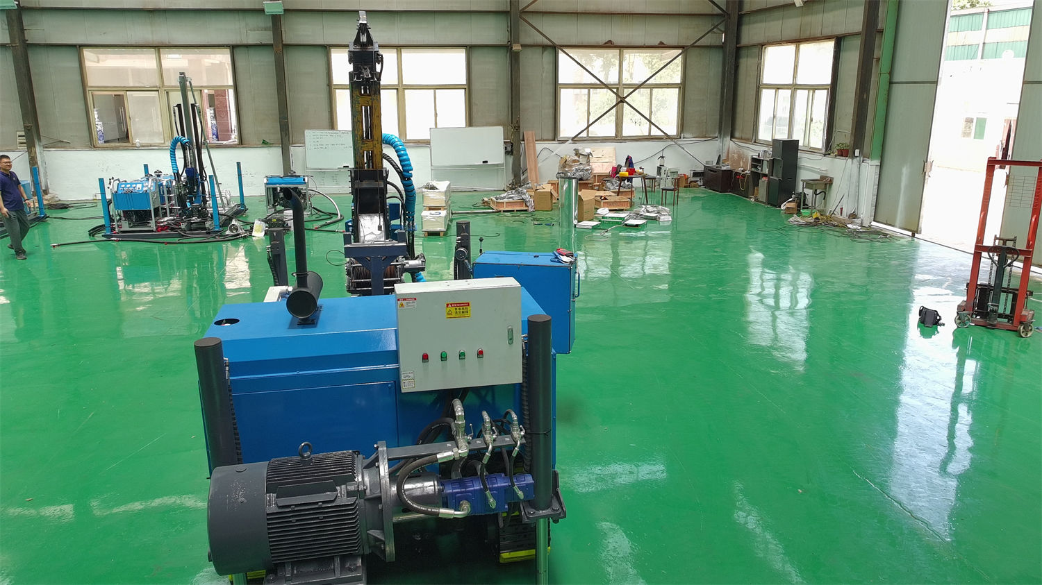
However, moving installation work forward in an integrated machine does not mean the total workload disappears. The overall dimensions, weight, and center of gravity in transport state still need to be checked section by section against road conditions; after arriving at the hole position, whether the crawler chassis can provide stable support, whether the platform is leveled, and whether additional support is needed on slopes must still be arranged according to site conditions.
What Do the Crawler Chassis and Folding Mast Each Handle?
The information describes the crawler chassis as having strong stability, high traction, and better adaptability to soft ground, suitable for mining area access roads, mountains, hills, gravel roads, and scenarios requiring frequent hole position changes. In actual operations, it handles short-distance movement between hole positions and positioning, rather than replacing highway transport. Long-distance relocation still requires transport vehicles; crawler travel only plays a role within the site or between adjacent hole positions.
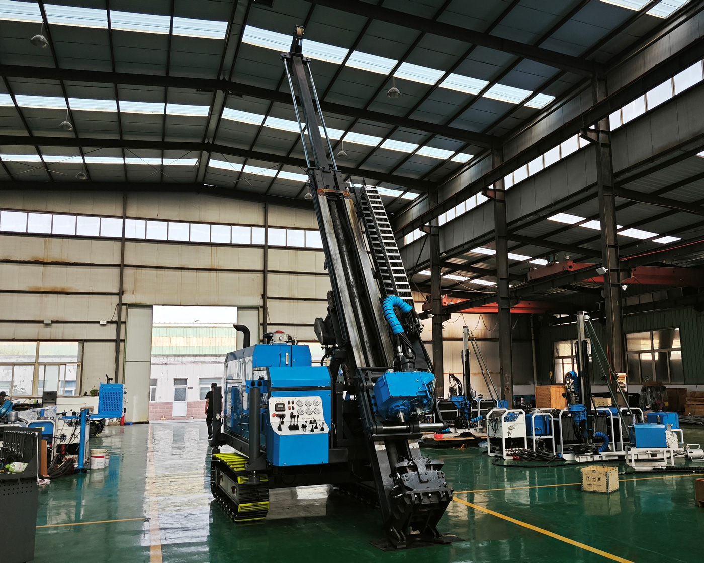
The folding mast corresponds to transport-state height and relocation difficulty. Folding the mast lowers transport height, which helps with road height limits and site entrances; when unfolded, it provides a feed stroke of 1.9 m, can handle 1.5 m drill rods, has a feed force of 42 kN and a pullback force of 130 kN. These values indicate single-pass advance length and in-hole lifting capability; during selection, they should be considered together with the drill rod length, hole depth, and in-hole friction you plan to use, and relocation ease should not be judged only by whether the mast folds.
Correspondence Between Inclined-Hole Layout and Coring Specifications
The information states that the CR600I supports drilling angles of 45°–90° and can perform vertical and inclined hole construction. For inclined ore bodies, vein-type ore bodies, fault structures, and alteration zones, reasonably selecting the hole inclination angle is intended to improve the probability of intersecting the target and avoid a drilling direction too parallel to the ore body strike. In projects with frequent relocation, inclined holes add another task: the mast attitude must be adjusted to the design angle at each hole position, which takes more attitude adjustment and verification time than vertical holes.
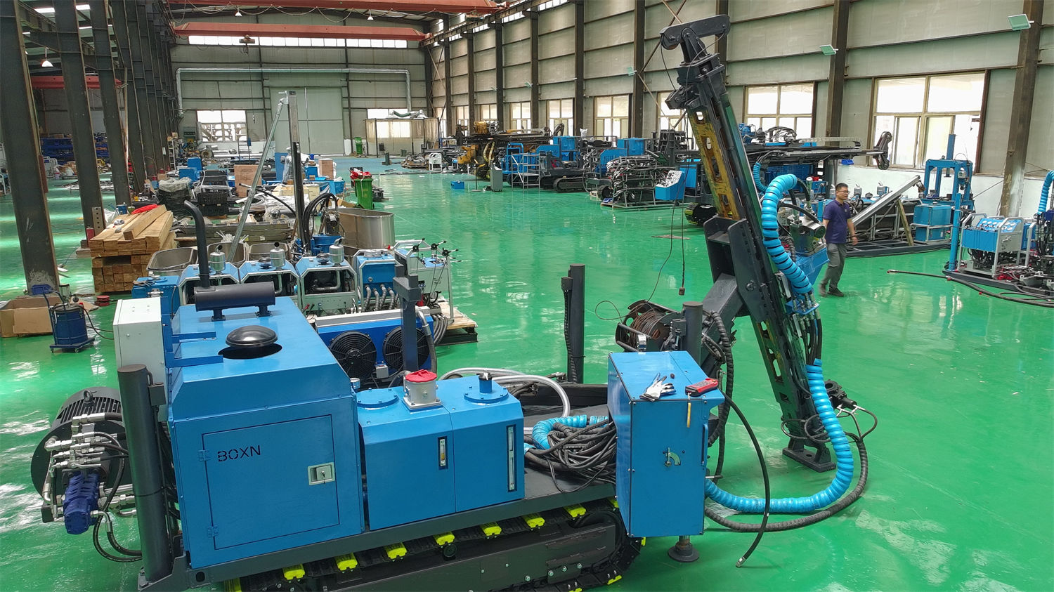
Regarding drilling depth specifications, the reference values given in the information are 800 m for B specification, 600 m for N specification, and 300 m for H specification. These three figures correspond to different drill rods and coring systems and cannot be understood as interchangeable. The actual achievable drilling depth is also affected by drilling angle, rock integrity, drill rod weight, in-hole tools, mud performance, borehole wall stability, and operating method. The specification range into which the planned hole depth falls should be determined first, and then whether this machine is within the corresponding range can be judged.
Supporting Conditions for Power, Mud, and Wireline Winch
The equipment uses a 4BTA3.9 type 3.9 L four-cylinder turbocharged direct-injection diesel engine, with rated power of 97 kW, rated speed of 2200 rpm, water cooling, and a 24 V electrical system. The main pump reference flow is 220 L/min at 20 MPa, the auxiliary pump reference flow is 60 L/min at 17 MPa, and cooling is air-cooled. These configurations correspond to the coordinated operation of the power head, feed, mast, travel, and auxiliary mechanisms, but continuous field construction also depends on fuel supply, heat dissipation environment, and hydraulic oil contamination control. The information mentions that the high-pressure filtration function is used to reduce wear of pumps, valves, and actuating elements caused by hydraulic oil contaminants; this is a maintenance condition and not a step that can be omitted on site.
The mud system has a reference flow of 100 L/min, pressure of 7 MPa, speed of 360 rpm, and power of 14 kW. After entering fractured zones, strongly weathered layers, fissure zones, or loss zones, mud return conditions will change, and mud viscosity, flow rate, and wall-protection measures need to be adjusted. In projects with frequent relocation, mud materials, mixing conditions, and waste mud treatment must also move with the hole positions; this workload will not be eliminated by an integrated chassis.
The wireline winch uses a 6 mm steel wire rope, with a rope capacity of 800 m, lifting force of 11 kN, and lifting speed of 98 m/min. Wireline coring reduces the auxiliary time of recovering the inner tube without pulling the entire drill string and is suitable for continuous coring in medium-deep holes. However, rope capacity and lifting force must match the planned hole depth and drill rod specifications; beyond the corresponding range, direct inference from the reference values in the information is not appropriate.
Which Conditions Push This Equipment Beyond Its Limits?
According to the information, the CR600I is positioned as a 600-meter-class fully hydraulic integrated crawler core drill rig for surface medium-deep hole coring. Its structural advantages are concentrated in complete-machine integration, crawler mobility, and rapid on-site deployment, making it suitable for mining areas, mountains, hills, forest roads, and exploration projects requiring frequent relocation. However, the following situations require separate verification and cannot be judged merely from the words “integrated”:
- When transport road width, slope, curve radius, bridge and culvert load capacity do not match the overall dimensions in transport state, crawler travel cannot solve the highway transport problem;
- When the hole position platform is insufficient in size or a slope cannot be leveled, the crawler chassis cannot replace reliable support; the information clearly indicates that equipment stability must not be maintained solely by friction between the crawler and the ground;
- When the planned hole depth exceeds the reference value for the corresponding coring specification, or when drilling angle and rock conditions make the actual drilling depth lower than the reference value, reassessment based on in-hole conditions is required;
- When mud materials, fuel supply, and waste mud treatment are not arranged along with the hole positions, the higher the relocation frequency, the more easily auxiliary steps hold back the drilling pace;
- When wireless remote control is required, the information states that it is an optional item, and remote control cannot replace on-site safety management; warning areas must still be set, command must be unified, and operation must begin only after confirming that no one is around the equipment.
These limits do not deny the value of the equipment under relocation conditions; rather, they show that “frequent relocation” is only one clue in selection. Hole depth specifications, the proportion of inclined holes, road conditions, and the degree of platform preparation jointly determine how much workload integrated equipment can save and in which stages the construction party will still need to make separate arrangements.
Items Worth Confirming One by One Before Starting Work
If you are comparing this type of equipment, it is advisable to first put the following information on paper: the correspondence between planned hole depth and coring specifications, the proportion of inclined holes and the design angle range, road conditions between hole positions and transport-state dimensions, platform dimensions and ground bearing capacity at each hole position, mud and fuel supply methods, and whether drill rod and casing specifications match the clamp's 127 mm through-hole diameter and common drill rod systems such as NQ, HQ, PQ, NTW, and HTW. Specific transport dimensions, overall weight distribution, and actual drilling depth performance under different formations are not covered by the information and need to be separately confirmed with the manufacturer or on-site technical personnel. Before these conditions are clarified, “integrated” should not be directly equated with “no relocation burden.”