












In the overall specifications of the WRT1000, the maximum drilling depth is listed as 1000 m. This figure appears in the information as a description of the rig's overall capability, not as a construction record of any specific well. It describes the upper limit of the hole depth range that this 1000-meter-class truck-mounted direct mast water well drilling rig is expected to cover. Whether it can actually reach this depth on a specific project depends on a set of conditions being simultaneously satisfied. Based solely on the publicly available WRT1000 information on this site, this article separates the conditions tied to the figure of 1000 m.
1000 m is an upper limit, not a default value
The information describes the WRT1000 as having a "maximum drilling depth of 1000 m." The same section also gives a hole diameter of 105–800 mm, a lifting force of 51/52 T, dual-speed rotary torque of 20000/10000 N·m, 194 kW diesel power, working air pressure of 1.65–8 MPa, air consumption of 16–96 m³/min, a 7 m feed stroke, and a recommended drill pipe diameter of 114 mm. These figures are not independent labels; the drilling depth lies within the range jointly defined by them.
Understanding 1000 m as "a depth achievable with any hole diameter and any formation" would ignore the constraints that hole diameter, formation, and supporting capability place on the actually achievable depth. This is reflected in the structure of the information itself: the hole diameter is given as a range, and the air pressure and air consumption are also given as ranges. A range means that different values correspond to different operating conditions.
The hole diameter value directly changes how difficult it is for 1000 m to hold
The hole diameter range of 105–800 mm spans a wide interval. The larger the hole diameter, the more the drilling tool load, casing weight, hole completion difficulty, and cuttings removal requirements all rise simultaneously at the same hole depth. The information states: larger hole diameters are suitable for larger well casings and pump types, but increasing the hole diameter simultaneously raises the drilling tool load, air compressor requirements, casing weight, and hole completion difficulty. In actual projects, the hole diameter should be reasonably selected according to water yield and well completion structure.
This means that a 1000 m drilling depth and an 800 mm hole diameter are not two conditions that can simply be added together. The information does not provide a table of corresponding achievable depths for different hole diameters. Therefore, before purchase, the target well diameter, well completion structure, and equipment capability should be placed together and confirmed in writing with the manufacturer, rather than citing the upper limit of hole diameter and the upper limit of drilling depth side by side.
The stability of the upper hole section is a prerequisite for whether the deep hole can continue to advance
The information explicitly states that for a 1000-meter deep well, the stability of the upper hole section is particularly important, because once collapse, diameter reduction, or casing problems occur early on, the risks and treatment costs of subsequent deep hole construction will increase significantly. The corresponding operating methods include using mud rotary drilling, casing, or other hole stabilization methods in the upper loose formations.
Soil layers, clay, sand layers, and gravel layers are classified in the information as upper formations suitable for mud rotary drilling. Deep wells often have to go through a continuous process of changes from loose overburden, weathered rock, fractured zones, and intact rock formations. The available route for the WRT1000 is to stabilize the hole with mud or casing in the upper section, and then switch to DTH after entering stable hard rock. For construction in fractured zones, the information gives the approach of reducing feed, strengthening hole cleaning, and promptly handling falling blocks and diameter reduction according to the hole wall conditions.
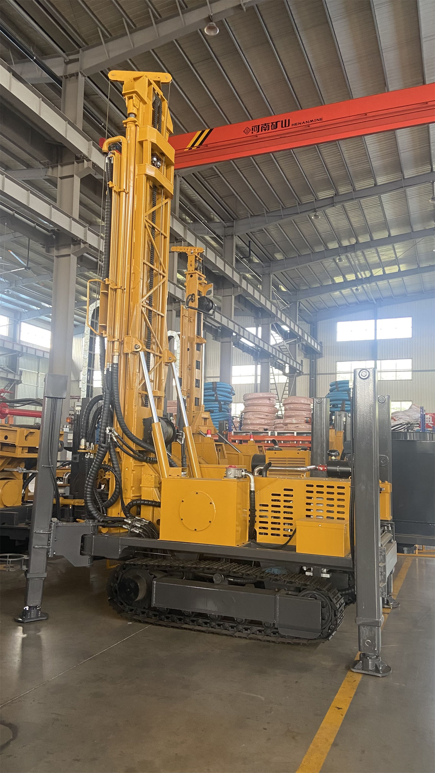
In other words, one prerequisite for 1000 m to hold is that the upper hole section does not get out of control before reaching the target depth. This part depends on the on-site formation and is not something the equipment alone can guarantee.
Under DTH conditions, air pressure and air consumption must match
For DTH down-the-hole drilling, the information recommends a working air pressure of 1.65–8 MPa and an air consumption of 16–96 m³/min. These two items are given as ranges, and the information specifically notes: 1000-meter-class deep holes and large-diameter hard rock place very high demands on air compressor pressure and displacement. During selection, a comprehensive judgment should be made based on the DTH hammer specifications, hole diameter, hole depth, altitude, and rock hardness, and one should not look only at the rated pressure.
1.65 MPa and 8 MPa are the two ends of this range, and 16 m³/min and 96 m³/min are likewise. The specific values within the range must be determined together with the DTH hammer specifications, hole depth, altitude, and rock hardness. The information does not provide conversion relationships among these variables, so before purchase this item is something that needs to be checked in writing in conjunction with the specific supporting equipment.
In addition, the information also mentions that after entering the main aquifer, the increase in water volume in the hole will affect the cuttings removal and circulation state of the DTH hammer. During construction, the depth of the main water-producing layers should be recorded, and the air supply, hole cleaning, and casing plans should be adjusted according to the water inflow. Strong aquifer sections and DTH cuttings removal can affect each other, and this also needs to be considered in deep holes.
Lifting force and drill string management correspond to the operating capability of the deep hole section
The information states that at a hole depth of 1000 meters, the self-weight of the drill pipe, the weight of the casing, and the friction of the hole wall all increase significantly. The WRT1000 provides a lifting force of 51/52 T and an axial pressure of 11 T, which can be used for deep hole tripping, DTH hammer recovery, some casing operations, and handling tools in abnormal hole sections.
The information also gives an operating boundary: when encountering continuously rising resistance during pull-out, the hole should first be cleaned and the downhole condition judged, rather than directly relying on the maximum lifting force to pull forcefully. This indicates that 51/52 T is an upper limit of capability, not a normal pull-out load that can be used at any time. The items to be continuously observed during deep hole construction are listed in the information as air pressure, torque, returned cuttings, returned water, and pull-out resistance.
Feed stroke and drill pipe length affect the organization of deep hole operations
The WRT1000 has a feed stroke of 7 m, can use 3 m or 6 m drill pipes, and recommends a drill pipe diameter of 114 mm. The information points out that 6 m drill pipes are suitable for long-cycle deep hole construction and can reduce the number of pipe connections; 3 m drill pipes are more suitable for sites with limited space, transportation, or manual operation conditions. The fast lifting speed of 28 m/min and fast feed of 42 m/min are mainly used for non-drilling movements.
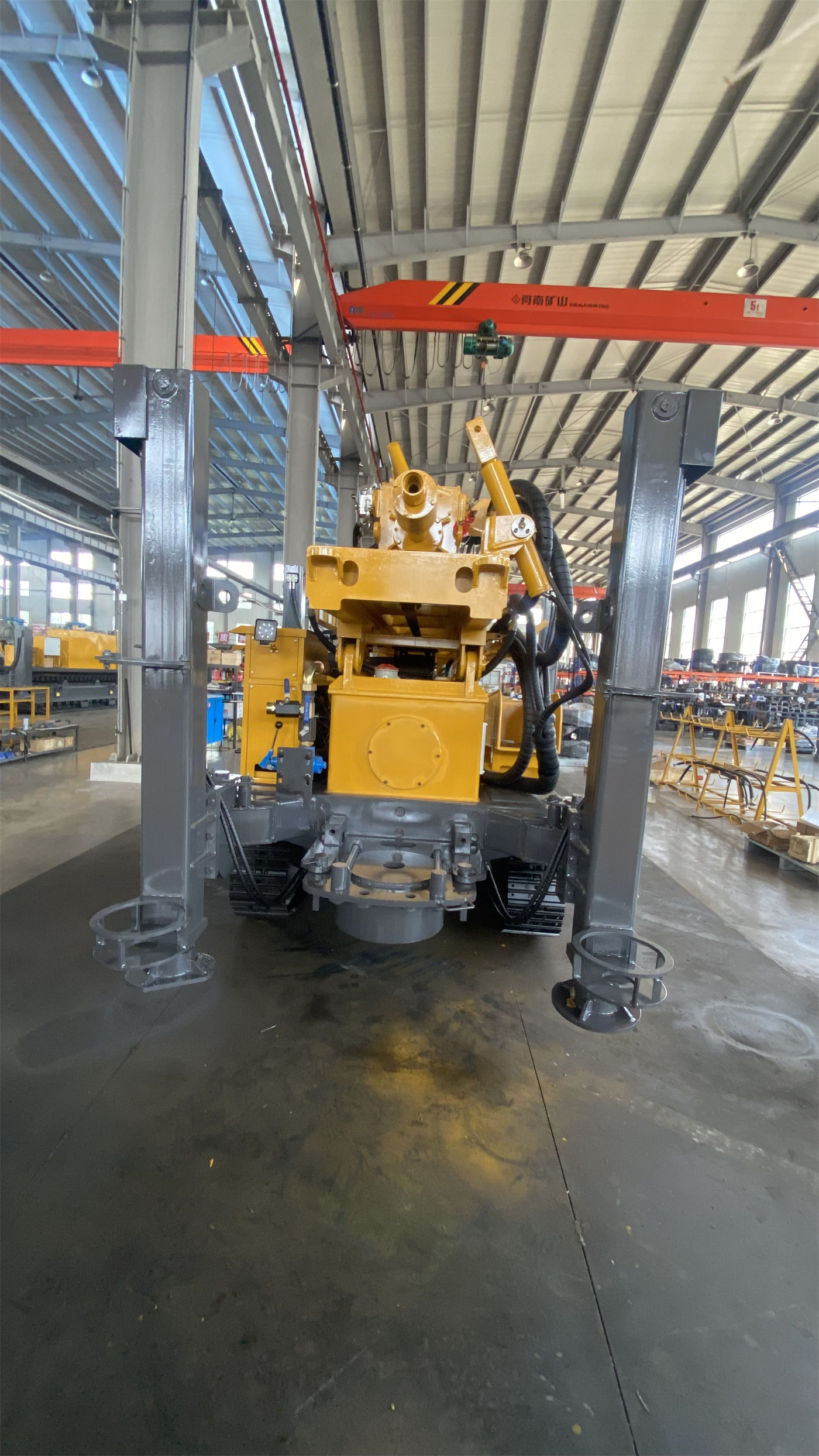
The choice of drill pipe belongs to the conditions at the construction organization level. The number of pipe connections affects the time arrangement of deep hole operations and does not change the upper limit of 1000 m itself, but in the matter of "whether a 1000 m drilling depth can be completed within the planned cycle," it is one of the factors that need to be considered.
The dual working conditions of rotary torque correspond to different hole sections
The information shows that the rotary drive is a dual-speed configuration of 20000/10000 N·m, corresponding to 70/140 r/min. Low speed and high torque are more suitable for large-diameter, hard rock, and high-friction hole sections, while the high-speed gear is suitable for stable formations with less resistance. Deep hole construction should dynamically adjust the working conditions according to rotary load, returned cuttings, and drilling tool wear.
The information does not provide a corresponding table of which gear is recommended for different hole diameters and rock formations. This part needs to be judged according to on-site returned cuttings and load conditions.
Overall transport conditions do not change the drilling depth, but they affect whether the rig can enter the site
The WRT1000 has an overall weight of about 26 T and transport dimensions of about 10.8 × 2.5 × 4.23 m. The information states that the truck-mounted structure improves road transfer efficiency, but the transport height of 4.23 m means that before entering the site, road height limits, bridges, overhead lines, factory gate openings, and other overhead obstacles must be verified. Under mining area road conditions, it is also necessary to confirm the road passage, slope, turning, and platform bearing conditions of the truck-mounted chassis.
These conditions do not participate in judging whether the 1000 m drilling depth holds, but they determine whether the equipment can reach the hole location. The actually achievable depth of a deep water well project is premised on the equipment first being able to enter the site and be stably positioned.
Matters not covered by the information that require written confirmation before purchase
The WRT1000 information on this site gives the overall capability range, but does not provide the following. Before purchase, these should be confirmed in writing with the manufacturer in conjunction with the specific project:
- The specific value of the achievable depth corresponding to the target hole diameter;
- Recommended switching depths between DTH and mud rotary drilling under different formation combinations;
- The values of 1.65–8 MPa air pressure and 16–96 m³/min air consumption under specific hole depths, altitudes, and rock hardness;
- The specific adjustment range of the air supply and hole cleaning plan according to the water inflow of strong aquifers;
- The available margin of the 51/52 T lifting force under different drilling tool combinations;
- The configuration requirements for casing, filter pipes, and water-stop sections under the target well diameter and well completion structure.
The figure of 1000 m appears in the information as the rig's maximum drilling depth. To use it as the expected well depth of a particular project, it is first necessary to confirm whether the above conditions are simultaneously satisfied.