












"Maximum drilling depth 750 m" is often the first figure looked at during selection, but in the WR750S specifications, the factor limiting actual working range is never this single number. Pulling out 750 m alone for comparison easily overlooks two accompanying sets of figures: 6 m drill pipe and 6 m casing, and the 105–450 mm hole diameter range; further on there are also 40 T lifting force, 6 T axial pressure, 176 kW power, 1.6–6 MPa working air pressure, and 16–75 m³/min air consumption. This article does not list parameters one by one, but instead presents three sets of numerical relationships that must be read together, and the deviations that easily arise when reading single figures alone.
Why 750 m, 6 m drill pipe, and 105–450 mm form one set
The drilling depth, drill pipe length, and hole diameter given in the specifications each constrain a different aspect: drilling depth is the upper limit of hole depth, drill pipe length affects the number of pipe connections, and hole diameter affects annular return velocity and required air volume. When the three are listed side by side, the actual hole depth capability cannot be established simply by taking 750 m.
At 750 m-class deep holes, the number of pipe connections is very high. The specifications state support for direct operation with 6 m drill pipe and 6 m casing, and the S in the model designation represents a telescopic mast, which can improve the overall transport profile in transport condition. The 6 m length only holds when read together with the telescopic mast—if not for a long-stroke or telescopic mast structure, the handling of 6 m drill pipe would be limited by mast height. Therefore "750 m + 6 m + telescopic mast" forms a complete condition, and if any one item is missing, the actual operability of 750 m must be re-evaluated.
The 105–450 mm hole diameter span should likewise not be read alone. A large hole diameter in a deep hole means a larger annular area, higher air volume demand, and also a greater torque reserve requirement. Writing both 105 mm and 450 mm as the capability range of the same machine actually indicates that this machine covers a wide range of working conditions, not that 750 m can be achieved at both hole diameters.
40 T lifting force must be viewed together with 6 T axial pressure and drill string weight
Lifting force and axial pressure are written separately in the specifications: lifting force 40 T, axial pressure 6 T. The two figures act in different directions—lifting force is responsible for tripping and lifting the drill string, while axial pressure is responsible for applying downward pressure to the drill bit. Together with drill string weight and hole wall friction, they determine whether normal tripping can be carried out at a 750 m deep hole.
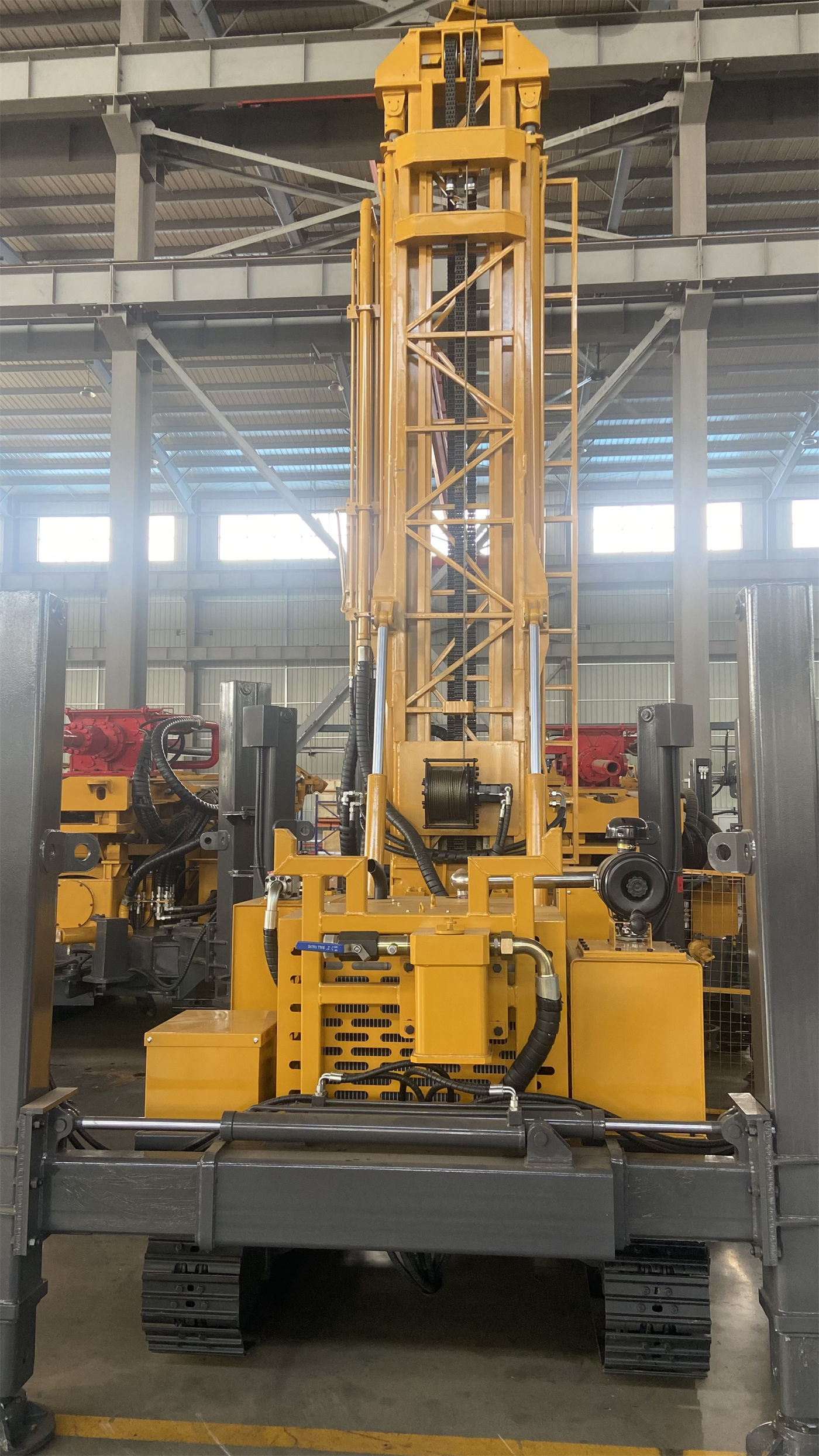
As hole depth increases, the weight of the entire string rises, and friction also increases noticeably. In the lifting force section, the specifications include a judgment: if abnormal pull-out resistance occurs, it should first be handled by judging hole cleaning, slow lifting, and in-hole conditions, avoiding treating maximum lifting force as the only solution. This statement itself is a methodological hint for reading parameters—40 T is the upper limit of equipment capability, not a handling method when stuck.
Appearing alongside the lifting force is a 2.5 T auxiliary winch, used for handling DTH hammers, drill pipes, casing tools, and on-site accessories. Only when this figure is placed together with the 40 T main lifting and 14 T overall weight does it form a complete picture of handling capability.
1.6–6 MPa air pressure must be paired with 16–75 m³/min air consumption
This is the place in the entire document most easily read in isolation. Working air pressure 1.6–6 MPa and air consumption 16–75 m³/min are respectively the upper pressure range and the flow range. The specifications clearly state: when pressure meets requirements but displacement is insufficient, insufficient impact and difficult cuttings removal may still occur.
Therefore these two figures belong to the same set, and an air compressor cannot be selected by looking at pressure alone. The upper limit of 6 MPa corresponds to the use requirements of medium-to-high pressure DTH hammers, but the specific match must satisfy both pressure and displacement. In 750 m-class deep holes, whether cuttings removal at the hole bottom is smooth directly affects torque and energy consumption, and settled cuttings and repeated crushing will add to the rotary load. The specifications mention in both the hard rock and weathered rock sections the need for continuous hole cleaning and adjustment according to in-hole conditions, which belongs to the same judgment chain as air pressure and air consumption.
It should be noted that the specifications do not give the specific lower air volume limits matched to DTH hammer models under different hole diameters and different hole depths; this part requires written confirmation from the manufacturer or air compressor supplier.
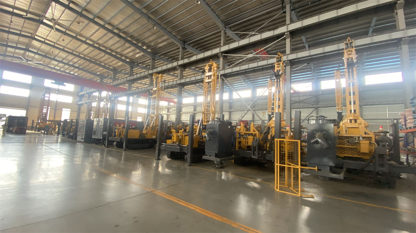
The two rotary torque gears and hole diameter belong to the same judgment
The specifications give two rotary configurations: 13000 / 6500 N·m and 15000 / 7500 N·m, with maximum rotary speeds of 95 / 190 r/min respectively. The appearance of two torque gears and two speed gears in the same rotary system itself indicates that which gear to use depends on specific working conditions, rather than simply taking the larger value.
The relationship between the adjacent hole diameter range 105–450 mm and rotary torque is not given in a corresponding table in the specifications. Therefore what can be said is: torque reserve favors large hole diameters, hard rock, and high-friction hole sections, while higher speed favors stages with lower resistance; the final match needs to be determined in combination with hole diameter, drilling tools, and the main rock formation. No calculation is made for parts not covered by the specifications.
Overall dimensions, weight, and outriggers should also be read as one set
The specifications give an overall weight of about 14 T, dimensions of about 6.64 × 2.25 × 2.67 m, a maximum gradeability reference of 21°, and a travel speed of about 3 km/h. These figures and the hydraulic outrigger stroke of 1.6 m form the same set: transport dimensions, gradeability, and outrigger adjustment range together determine what sites this machine can enter and what platforms it can work on.
The specifications also note that sufficient-area pads should be used on soft ground, and road and platform bearing capacity should be confirmed before relocation. These are usage conditions, not equipment capability, so looking only at dimensions and weight cannot determine whether a specific site is feasible.
Figures that need to be classified separately
- Fast lifting 31 m/min and fast feed 65 m/min are auxiliary action speeds, not the same category of indicators as drilling capability.
- Optional mud pumps, centrifugal pumps, generators, and foam pumps fall within the accessory range and do not represent standard configuration.
- Air consumption 16–75 m³/min is the recommended range for the equipment, not equal to the actual output of the selected air compressor.
Matters requiring written confirmation before purchase
- The drilling tool combinations and achievable depths corresponding to 750 m drilling depth at different hole diameters (105–450 mm).
- The required air compressor displacement and DTH hammer models under 1.6–6 MPa air pressure and 16–75 m³/min air consumption.
- The standard configuration and optional conditions corresponding to the two rotary torque configurations.
- The specifications, thread forms, and compatibility with existing tools for 6 m drill pipe and 6 m casing.
- The text at the end of the specifications mentioning 750 m deep hole construction is incomplete; the complete version of relevant construction conditions should be obtained from the manufacturer.
Main Technical Parameters
| Item | Specification Value |
|---|---|
| Maximum drilling depth | 750 m |
| Drilling diameter | 105–450 mm |
| Lifting force / axial pressure | 40 T / 6 T |
| Rotary torque / speed | 13000 / 6500 N·m; 15000 / 7500 N·m; 95 / 190 r/min |
| Engine | 176 kW Weichai |
| Drill pipe / casing | 6 m / 6 m, recommended 102 mm drill pipe |
| Working air pressure / air consumption | 1.6–6 MPa / 16–75 m³/min |
| Fast lifting / fast feed | 31 m/min / 65 m/min |
| Auxiliary winch | 2.5 T |
| Travel speed / gradeability | About 3 km/h / reference 21° |
| Hydraulic outrigger stroke | 1.6 m |
| Overall weight / dimensions | About 14 T / about 6.64 × 2.25 × 2.67 m |
The structure of this document is itself a hint: the same capability is often jointly limited by two or three figures. When reading 750 m, also look at 6 m and 105–450 mm; when reading 40 T, also look at 6 T and drill string conditions; when reading 6 MPa, also look at displacement. The document does not write out the boundary conditions of every item in full, so during the selection stage it is still necessary to confirm the corresponding relationships item by item with the manufacturer, rather than treating each maximum value as an indicator that can hold simultaneously on its own.