












The WR500RCE is a 500 m class crawler-mounted air-lift reverse circulation water well drilling rig, equipped with a 132 kW diesel engine, 300 kN lifting force, and 8000–12000 N·m rotary torque, with a hole diameter of 140–400 mm. The crawler chassis has a travel speed of approximately 2.5 km/h, a reference gradeability of 30°, and a total machine weight of approximately 12 T. Placing such a machine into a deep water well project dominated by hard rock requires preparation beyond just the equipment itself. The following preparation items are organized in the order of site advancement. Parameters that can be verified are stated directly, while items not covered by the materials are listed separately as matters requiring written confirmation from the manufacturer or project owner.
Why preparation priorities differ for hard rock deep water wells
Under hard rock conditions, the primary drilling method for this rig is the DTH hammer, with air-lift reverse circulation responsible for carrying cuttings from the hole bottom back to the surface through the inside of the drill pipe. The matching requirements are stated specifically: recommended working air pressure 1.7–3.5 MPa, air consumption 17–42 m³/min; as hole depth increases, hole diameter enlarges, rock formation hardens, or construction altitude rises, the required displacement will increase accordingly. This means site preparation must revolve around a longer chain—whether the air compressor can supply air stably, how water and air hoses are laid, how cuttings are discharged, and whether transport roads can bear a 12 T crawler machine. Each item determines the construction pace before the hole is even started.
Transport and lifting preparation before entry
The WR500RCE has transport dimensions of approximately 6300 × 2100 × 2500 mm, working dimensions of approximately 4000 × 2900 × 6800 mm, and a transport weight of approximately 12 T. Before transport, confirm vehicle load capacity, loading fixation points, and road height restrictions along the route—especially the nearly 6.8 m height when the mast is raised in working condition, which is different from transport height and requires dedicated mast-raising space on site.
Lifting and unloading methods are also pre-entry preparation items, not issues to be studied after arrival. The following must be confirmed jointly with the carrier and site management before shipment:
- Whether loading and unloading use lifting or self-propelled ramps depends on whether the site has a compliant unloading ramp, to be judged based on actual conditions;
- Ground bearing capacity between the unloading point and the hole position; soft soil and wet, slippery areas should be traversed cautiously to avoid getting stuck;
- Bridges, culverts, turning radii at intersections, and high-voltage line clearances along the transport route must be confirmed according to actual road conditions;
- The auxiliary winch has a 20 kN lifting force and can be used for moving DTH hammers, drill pipes, casing tools, and some site accessories. Rated loads should be controlled during lifting, and personnel should be kept away from beneath suspended loads and from areas where wire ropes are under tension.
Travel and positioning conditions after crawler entry
The crawler structure is better suited to mining area gravel roads, rural roads, and generally uneven ground. The travel speed of approximately 2.5 km/h means movement between hole positions follows a "slow shuffle" rhythm. When scheduling multiple hole positions, movement time must be included in the construction period rather than assuming the machine can quickly relocate between holes.
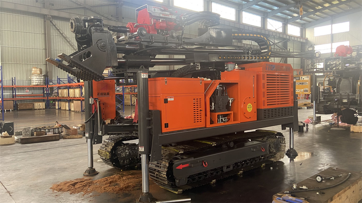
The reference gradeability of 30° is an equipment specification provided in the materials, but it does not mean any slope within 30° on site can be traversed directly. Lateral stability of crawler equipment on slopes, slope surface material, and post-rain conditions all affect actual traversability. The site should conduct a survey before deciding on travel routes.
How to implement air compressor and air circuit on site
Air-lift reverse circulation relies on compressed air to establish reverse flow in the inner pipe, carrying cuttings and drill spoil from the hole bottom back to the surface through the inside of the drill pipe. The air compressor is the key matching equipment for this system, with recommended working pressure of 1.7–3.5 MPa and air consumption of 17–42 m³/min. The preparation phase needs to address the following:
- Matching air compressor displacement with actual hole depth, hole diameter, and rock hardness—verify with the manufacturer based on project conditions; do not estimate solely from equipment rated parameters;
- Laying path, number of joints, and spare joints for high-pressure air hoses; high-pressure air hoses are components that should be inspected before daily start-up;
- Whether optional items such as oil mist lubricators and foam pumps are required configurations for this project, to be judged based on formation air leakage conditions;
- Daily arrangement for DTH hammer lubrication, which along with high-pressure line wear inspection is part of daily checks.
It should be noted that the materials on this site only provide the recommended air pressure and air consumption range for the air compressor, without specifying particular air compressor models, brands, or quantity requirements. This part should be confirmed in writing by the purchaser with the manufacturer based on project hole depth, hole diameter, and altitude conditions.
Water source, slurry discharge, and cuttings handling
Air-lift reverse circulation primarily uses pneumatic force for spoil discharge, but hard rock deep water well sites typically still require water for DTH hammer cooling, hole mouth dust suppression, and auxiliary operations. During preparation, confirm the water source location, supply capacity, and supply method to avoid interruptions due to water shortage during drilling.
Cuttings returned to the surface require stockpiling and disposal arrangements. Mining areas and remote sites should consider the distance between the stockpile area and the hole mouth, whether containment or settling areas are needed, and how mud and cuttings are handled after mixing during the rainy season. The materials do not provide specific specifications for settling ponds or slurry discharge systems; this falls under matters requiring confirmation by the project owner based on environmental requirements and site conditions.
Site layout and safety distances
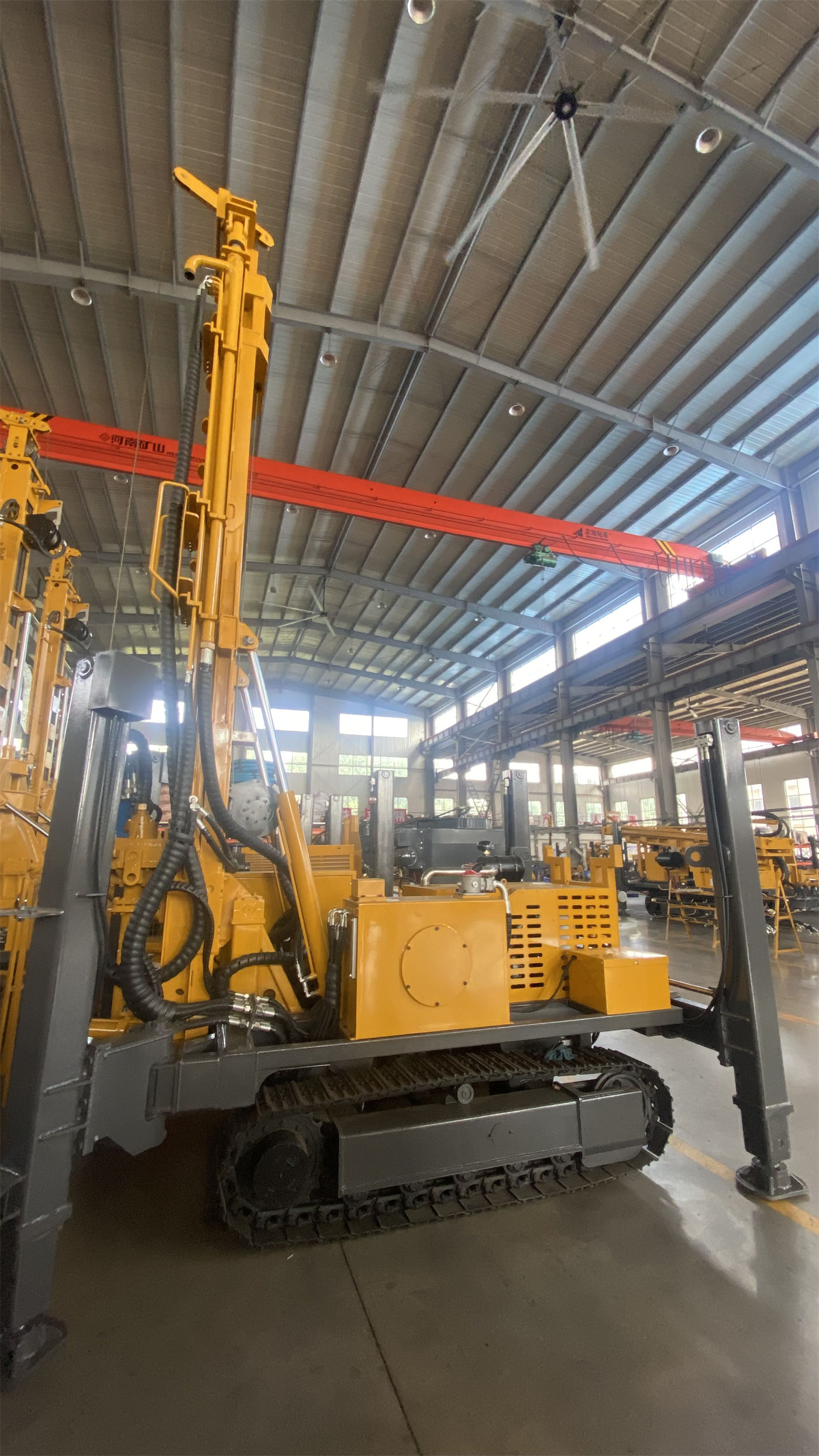
In working condition, the overall machine dimensions are approximately 4000 × 2900 × 6800 mm. After the mast is raised, a dedicated working envelope is required. When laying out the site, consider:
- Spacing between hole mouth and mast, drill pipe storage area, and operating space for tripping drill tools in and out;
- Relative position of air compressor and drilling rig; air hoses should be as short as possible and adjusted according to actual site conditions;
- Diesel engine exhaust direction, fuel supply point, and firefighting equipment locations;
- Separation of personnel access routes from lifting operation areas to prevent non-operating personnel from entering beneath suspended loads.
When encountering faults, fracture zones, and fissured formations, hole caving, hole shrinkage, air leakage, and stuck drill pipes may occur. The site should prepare necessary casing and foam materials, and adjust drilling methods when necessary. These are responses during construction, but available tools and materials should be prepared before entry rather than mobilized after problems occur.
Personnel, operation handover, and spare parts
When equipment enters a hard rock deep water well project, a period of operational and process familiarization is typically required. During preparation, it is recommended to clarify:
- Division of responsibilities and handover methods among site managers, operators, and auxiliary workers;
- Fixed daily pre-start inspection procedures: high-pressure air hoses, joints, safety ropes, swivel head, crawler, mast, and hydraulic system;
- Record items requiring continuous observation during drilling: air pressure, returned cuttings, returned water, and torque changes;
- Post-completion wrap-up: clean drill tools and reverse circulation channels, check DTH hammer lubrication, drill pipe seals, and high-pressure line wear;
- Minimum available quantities of wear parts and spare parts; specific types should be confirmed with the manufacturer based on project formations.
Matters not covered by materials requiring confirmation with manufacturer or project owner
Classifying the above preparation items into two categories can help avoid information gaps between procurement and site operations.
| Category | Specific Content | Basis Status |
|---|---|---|
| Can be prepared directly from site materials | Transport dimensions, working dimensions, total machine approximately 12 T, travel speed approximately 2.5 km/h, gradeability 30°, working pressure 1.7–3.5 MPa, air consumption 17–42 m³/min, hole diameter 140–400 mm, maximum drilling depth 500 m | Specific values provided in materials |
| Requires verification with manufacturer based on project conditions | Air compressor model and quantity, high-pressure air hose specifications and length, whether oil mist lubricators and foam pumps are necessary, specific specifications and quantities of drill pipes and casing | Materials provide only ranges, not specific configurations |
| Requires confirmation by project owner or carrier | Road height restrictions and load capacity, unloading method, site ground bearing capacity, mast-raising space, water source and slurry discharge arrangements, environmental disposal requirements | Site conditions not covered by equipment materials |
The WR500RCE's 500 m drilling depth and crawler chassis make it suitable for medium-to-deep water wells, agricultural irrigation, mining area water supply, and DTH drilling in relatively intact rock formations such as granite, basalt, and limestone. Final well depth should still be determined by hydrogeological data and the actual water-producing layer; equipment capability is only part of the drilling platform. Actual results also depend on air compressor displacement, hole diameter, drill pipe seals, and formation conditions. Verifying these conditions item by item during the site preparation phase is more realistic than supplementing matching equipment after the hole is started.