












The term "mini crawler water well drill" points to two sets of characteristics: a compact body and crawler travel. It does not describe an upper limit of capability, so it cannot be reversed to infer that "it can get into any place." To clarify what kind of sites it is better suited for, "suitable" needs to be broken down into several conditions that can be checked against. The WR220SE information on this site is relatively complete, so it is used below as a reference sample for item-by-item comparison; other compact crawler models can be self-checked in the same order.
"Mini crawler" describes access and travel, not drilling capability
The WR220SE overall dimensions are approximately 3950 × 1750 × 2250 mm, the overall weight is approximately 4.7 T, and the loading width is 2.6 m. These figures determine several things: whether it can pass along a certain road, whether it can stop at a certain work position, and how wide a carriage is needed for loading and transport. They do not determine how deep it can drill or how large a hole diameter can be opened.
The boundaries on the drilling side lie in another set of parameters: maximum drilling depth 220 m, drilling diameter 140–254 mm, and the drilling method is water-air dual-purpose. The two sets of parameters answer different questions; looking at them together can easily lead to conclusions that do not match the site.
Site access: the limiting factor is often width, not length
A body width in the 1700-plus mm range is the reason this type of equipment is repeatedly mentioned in rural scenarios. The information states that the applicable ground includes village roads, farmland, orchards, gravel ground, and generally uneven sites, which can be compared from the two angles of access and parking position:
- Access road: a compact body can lower the requirement for road width, but whether it passes still needs to be judged according to actual road width, turning radius, roadbed bearing capacity, and overhead obstacles. The information does not give the minimum turning radius or ground clearance.
- Work position space: points with very little surrounding space are easier to park and adjust the hole position, but space for drill pipe operation and cuttings discharge still needs to be left around the hole opening, and this also needs to be measured on site.
- Transport: a loading width of 2.6 m and an overall weight of about 4.7 T belong to the transport profile of small and medium-sized equipment. The actual vehicle used and the securing method should be confirmed according to road conditions and transport regulations.
Travel and climbing: what 2.5 km/h and the reference 30° each indicate
These two figures are easily understood as a combined meaning. A travel speed of about 2.5 km/h describes transfer efficiency—moving positions within a site and short-distance transfers will not be too slow—but it cannot be inferred from this that it can travel long distances on its own. The maximum climbing ability reference of 30° describes the slope limit, while whether it can actually climb still depends on whether the ground is wet and slippery, whether the slope is continuous, the center-of-gravity state, and whether the mast is in the transport position.
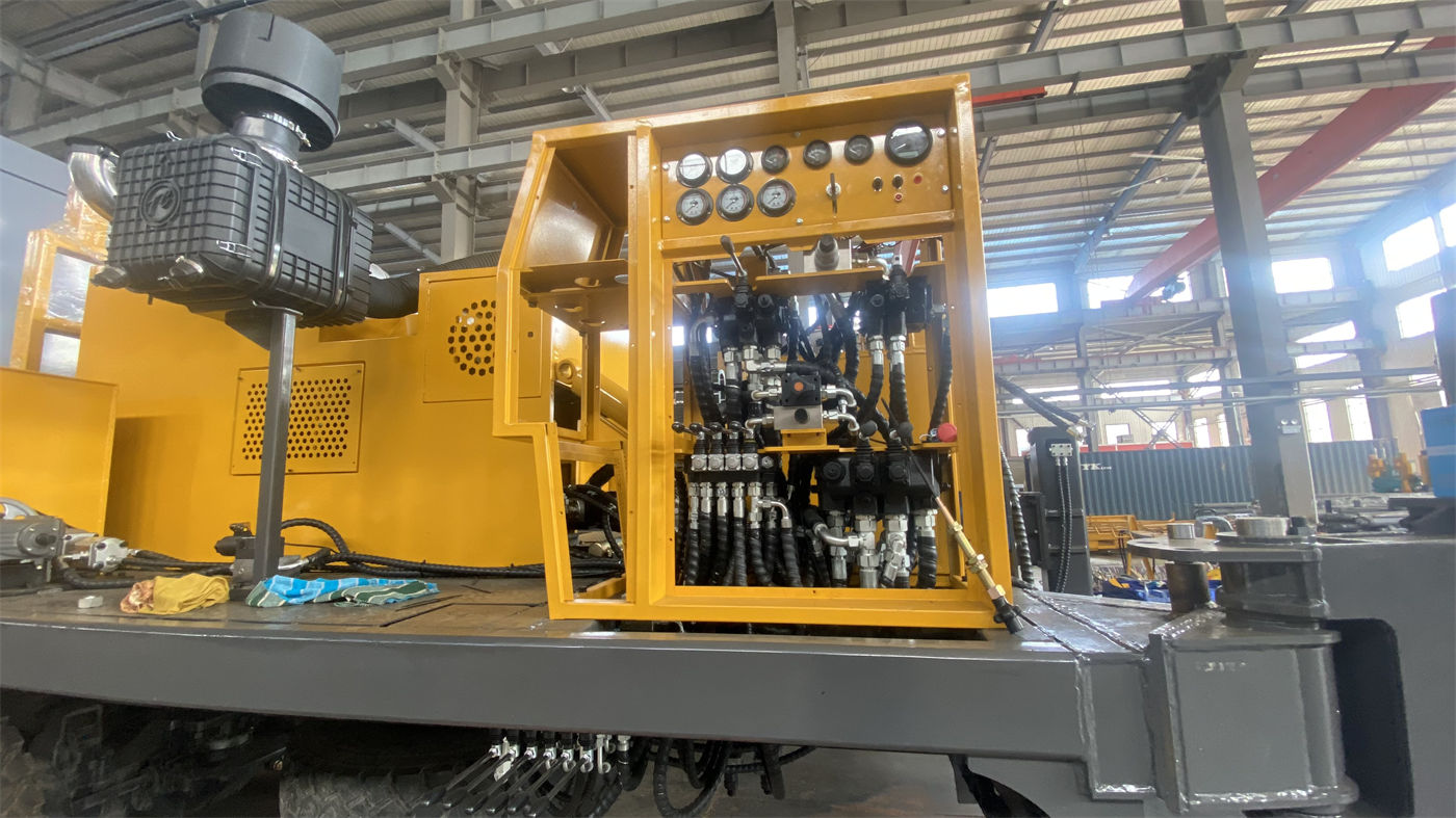
There is another note in the information worth carrying over directly: before actual climbing and transfer, judgment should be made according to the degree of ground wetness and slipperiness, slope, and center-of-gravity state, and the mast should be in a safe transport position. The essence of this statement is that 30° is a reference value, not access permission.
Support and leveling: the 1.4 m high outrigger is a conditional capability
The high outrigger stroke is 1.4 m, and its role is to help the equipment complete support and leveling on mildly uneven sites. The key word here is "mild." The information also gives the handling direction for soft ground: add pads to prevent the outriggers from sinking.
From this, the boundary of this type of site condition can be drawn: in sites such as farmland edges, orchards, courtyards, and within enclosures, if there is only mild undulation, the outrigger stroke can be useful; if the surface is soft or there is backfilled soil, solve the support problem first, then discuss opening the hole. Before formal drilling, the stability of the whole machine and the mast direction should be confirmed to avoid ground settlement affecting hole deviation and drilling safety.
Water-finding margin: under what circumstances does the 220-meter class constitute an advantage
The information lists the typical applications of the WR220SE as farmland irrigation wells, orchard water wells, nursery water supply, greenhouse water use, rural household water wells, small public wells, village-level water supply, livestock drinking water wells, and small water supply projects in pastoral areas. Looking at these scenarios together, the common points are that the single-hole scale is not large and the water use points are dispersed.
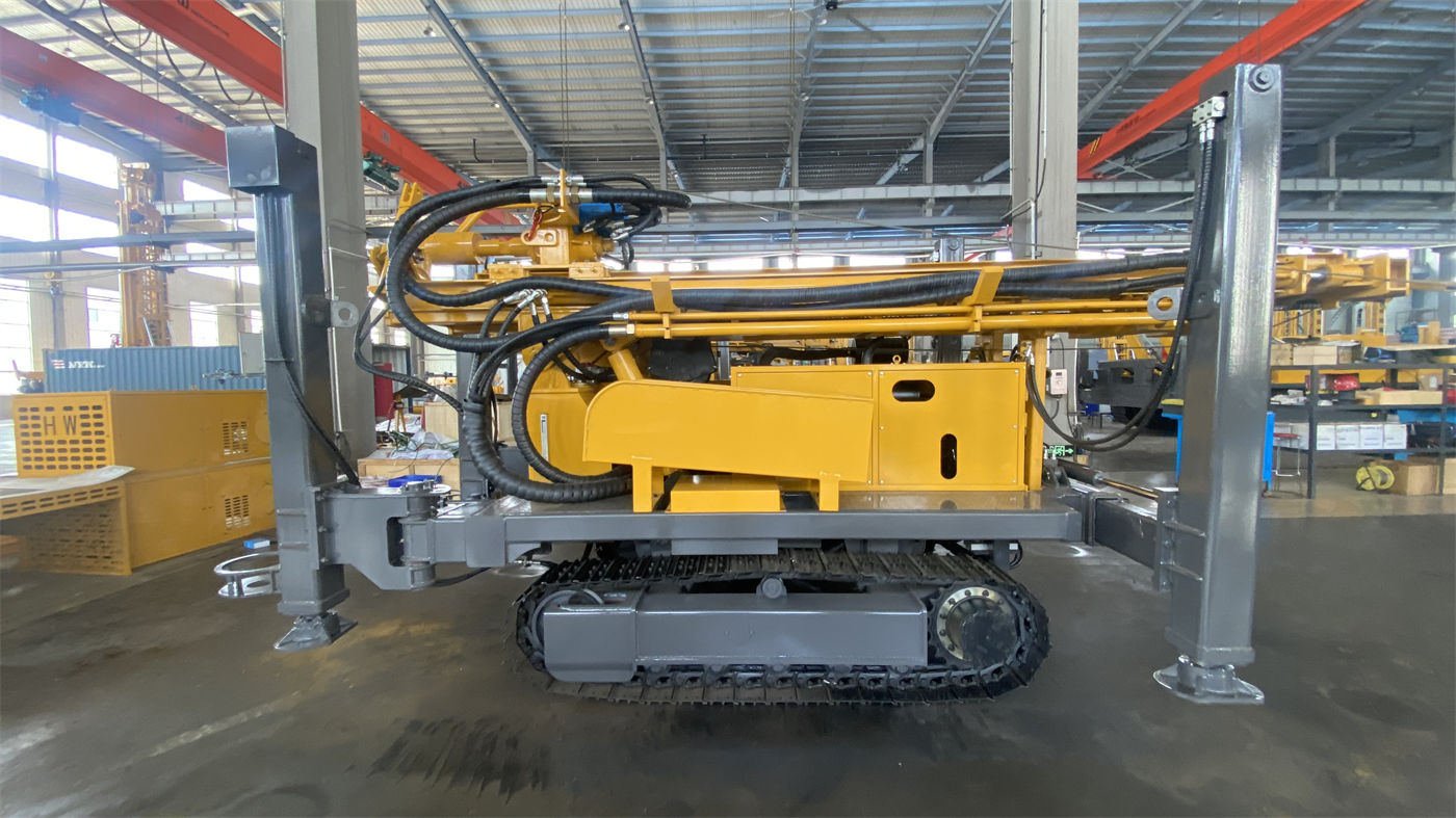
The difference between the 220-meter class and smaller equipment is described in the information as "a larger water-finding margin," with special mention of hilly areas, dry farming areas, and seasonal irrigation areas where groundwater levels vary greatly. This is a judgment that requires preconditions: the margin is only useful when the aquifer position is deeper than expected. The actual well depth should still be determined according to local hydrogeological data and aquifer position. Conversely, if the local completed well depth has long been stable in a relatively shallow range, this margin may not be a decisive factor.
Water-air dual-purpose: site conditions also include "whether air can be used"
The WR220SE supports water-air dual-purpose drilling and can select the process according to formation conditions: for soil layers, clay, and loose overburden, the focus is on hole stabilization and cuttings discharge; after entering weathered rock or relatively intact rock formations, pneumatic drilling can be used with a down-the-hole hammer and air compressor. The information clearly states that water-air dual-purpose is not a simple switch.
This means there is another item in the site conditions: whether the pneumatic process can be implemented. The air compressor reference given in the information is working pressure 1.7–2.5 MPa and air consumption 17–31 m³/min, selected according to hole diameter, down-the-hole hammer specifications, target hole depth, altitude, and rock hardness. Whether the site has space to place the air compressor, whether the air supply distance is reasonable, and whether additional transport capacity is needed should all be confirmed before starting work.
| Site condition | Description supported by the information | Still needs separate confirmation |
|---|---|---|
| Access road | Body about 1750 mm wide, a compact structure | Actual road width, turning, bearing capacity, and overhead obstacles |
| Site flatness | Compact body suitable for rural and agricultural environments | Working face depth and cuttings discharge space at the hole opening |
| Slope | Maximum climbing ability reference 30° | Wet and slippery conditions, continuous slope, and center-of-gravity state |
| Surface support | High outrigger stroke 1.4 m | Soft soil thickness and pad scheme |
| Water-finding depth | Maximum drilling depth 220 m | Actual local aquifer position and well depth |
| Power source | Yuchai 48 kW diesel engine, can be independent of a fixed power grid | Fuel supply distance and site emission conditions |
Diesel power and field sites
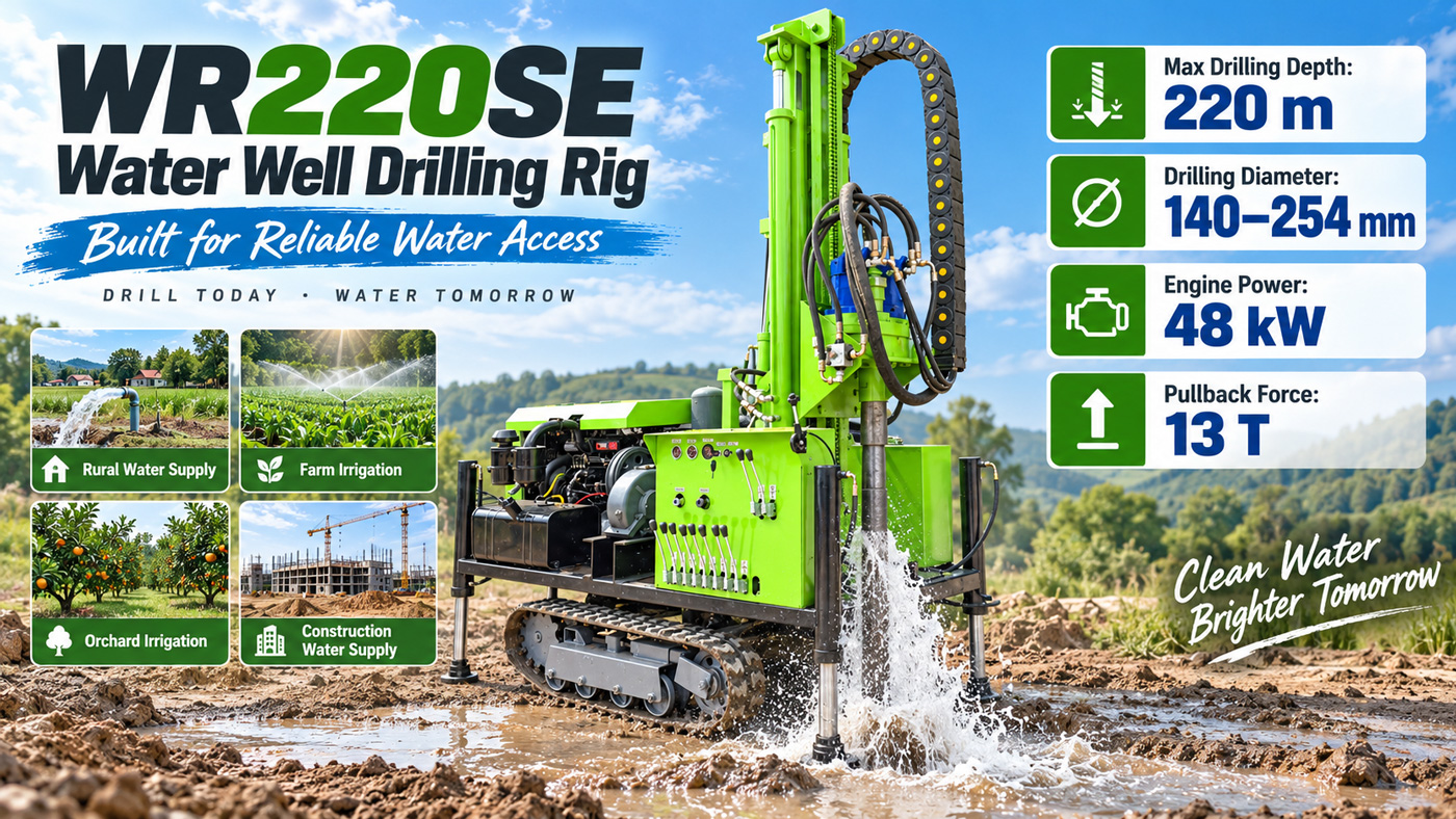
The power configuration stated in the information is a Yuchai 48 kW engine, and it mentions that diesel power enables the equipment to work independently on sites without a fixed power grid, making it suitable for relatively remote agricultural and livestock environments. The judgment this supports is: whether the site has stable mains electricity does not constitute a hard precondition for the equipment. The judgment it does not support is that any field site can be accessed smoothly—that is a matter of access conditions and has nothing to do with the power form.
Two notes related to the site during construction
There are two notes in the information related to the site and formation state. They are explanatory in nature, not operating instructions. First, sand layers and sand-gravel layers are prone to hole collapse, drill burial, and hole diameter enlargement, more obviously when groundwater is relatively abundant; for such formations, priority should be given to hole wall protection and casing follow-up. Second, when encountering fissures and fractured zones, the advance speed should be reduced, continuous hole cleaning should be maintained, and changes in wind pressure and return water should be observed. These two points also remind the selection party in reverse: explaining the main formation types of the site in advance is more useful than explaining the downhole situation afterward.
In addition, the rapid lifting speed of 30 m/min and rapid advancing speed of 60 m/min describe rapid movement of the power head and drill pipe operation, and cannot be read as actual drilling speed. The real footage efficiency depends on formation hardness, hole diameter, drilling tool wear, air compressor capacity, and operating method.
Judgments the information can and cannot support
In summary, the conclusion that can be drawn from the public information is: mini crawler water well drills such as the WR220SE are better suited for agricultural and rural scenarios with restricted access roads, narrow work positions, small single-hole scale, dispersed water use points, and possible fluctuations in groundwater level. The information states the applicable ground as village roads, farmland, orchards, gravel ground, and generally uneven sites, which can serve as the basis for this judgment.
Judgments the information cannot support include: whether a specific road or ramp can be passed; the final well depth and completion effect of a certain well; actual drilling efficiency under specific formations; and whether equipment needs to be configured separately in addition to the pneumatic process. These should be determined after combining on-site working conditions, local hydrogeological data, and manufacturer confirmation. Due to differences in actual geological conditions, downhole tools, drilling angle, and operating method, the final drilling efficiency, drilling depth, and well completion effect are subject to on-site working conditions.