












When comparing 350-meter-class equipment against a specific project, a common approach is to first look at the nominal drilling depth: the project is expected to complete a 300-meter well, the equipment is rated at 350 m, so it is judged sufficient. This judgment covers only one of the conditions. 350 m is the drilling depth upper limit of this machine; the project hole depth falling within the upper limit is only a necessary condition. If any one of hole diameter, drill pipe specification, downhole resistance, well completion structure, or relocation conditions is mismatched with the equipment capability, the conclusion of "sufficient" will not hold.
The following breaks down the stages in the order of judgment, with the sample taken from the publicly available information of the HJH WR350SE on this site. The order starts from the hole itself, then moves to the drill string, feed and rotation, power support, and site. Each step marks the judgments the materials can support and the content that still needs verification.
Step 1: Hole depth and hole diameter must be viewed as a set
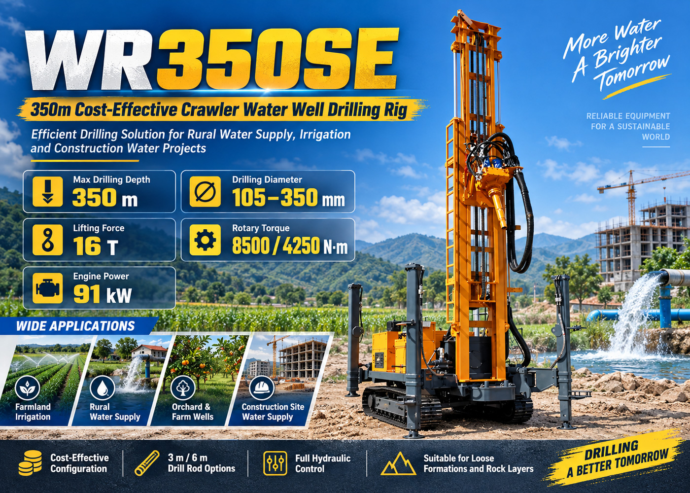
The WR350SE has a maximum drilling depth of 350 m and a drilling diameter of 105–350 mm. These two values are not independent indicators but a set of constraints that must hold simultaneously: how deep it can cover at a certain hole diameter also depends on the formation and well completion structure.
The drilling diameter of 105–350 mm corresponds to the hole-forming range. The well casing specification, submersible pump outer diameter, and planned water output determine the final hole diameter, and only then can it be discussed whether this diameter can be smoothly advanced to the design hole depth under the project's formation conditions. The materials do not provide a tiered explanation of different hole diameters and corresponding achievable depths, so it cannot be inferred from "350 m + 350 mm" that "a 350 mm hole diameter can also drill to 350 m." This point needs to be confirmed through hydrogeological data and with the manufacturer.
The applicable formation information states "loose formations and rock formations." This is a broad statement; the thickness of the overburden, rock hardness, and degree of fracture development all affect the actual final hole depth. For the same machine, how deep it can go in a hole dominated by overburden and one dominated by hard rock are not the same question.
Step 2: Drill pipe and casing specifications are determined first
The WR350SE supports two drill pipe lengths, 3 m and 6 m, with recommended drill pipe diameters of 89 / 102 mm. This specification choice affects more than just the number of pipe connections.
- 3 m drill pipe: each piece is shorter and lighter, making it easier to arrange for projects with limited transport conditions, narrow sites, or steep road slopes; the cost is more connections and disconnections, increasing the proportion of auxiliary time.
- 6 m drill pipe: reduces the number of connections, allows longer continuous drilling time, and suits an organization that needs to complete a longer footage in one day; the requirements for site clearance and transport envelope increase accordingly.
The choice between 89 mm and 102 mm drill pipe diameters needs to be checked together with hole diameter, hole depth, and working torque, and cannot be based only on "the thicker the better." The materials do not provide pairing recommendations for different pipe diameters with different hole diameters and hole depths; this part should be raised during inquiry.
Casing operations are related to lifting capacity. The materials state that the 16 T lifting force "can meet the tripping, DTH hammer recovery, and part of casing operations in most 350-meter-class water well projects," where "part of casing operations" is a qualified statement; the specific casing specifications and casing running depth need to be verified separately.
Step 3: Lifting force, torque, and rotation speed must be read together
The feed and rotation section of this machine has several sets of values: lifting force 16 T, rotary system maximum torque 8500 / 4250 N·m, corresponding maximum rotation speeds 80 / 160 r/min, fast lifting 30 m/min, fast feed 55 m/min.
| Parameter | Value in materials | Role in judgment |
|---|---|---|
| Maximum drilling depth | 350 m | Capability upper limit, not the construction target for every well |
| Drilling diameter | 105–350 mm | Determined together with casing, submersible pump, and water output |
| Lifting force | 16 T | Tripping, DTH hammer recovery, part of casing operations |
| Rotary torque | 8500 / 4250 N·m | Corresponds to two rotation speed conditions, selected according to hole section resistance |
| Rotation speed | 80 / 160 r/min | Appears in pairs with torque, not used alone |
| Power | 91 kW | Shared by rotation, feed, travel, and auxiliary actions |
| Working air pressure | 1.2–3.5 MPa | DTH condition, checked together with air consumption |
| Air consumption | 16–55 m³/min | Determines the air compressor configuration method |
Fast lifting at 30 m/min and fast feed at 55 m/min describe the speeds of non-drilling actions, used for drill pipe handling, power head return, and tool adjustment. The materials also give a reference drilling efficiency of 10–35 m/h and clearly state that actual results are related to lithology, drilling tools, air compressor, and operator experience. Treating 30 m/min as the footage rate is a common misreading.
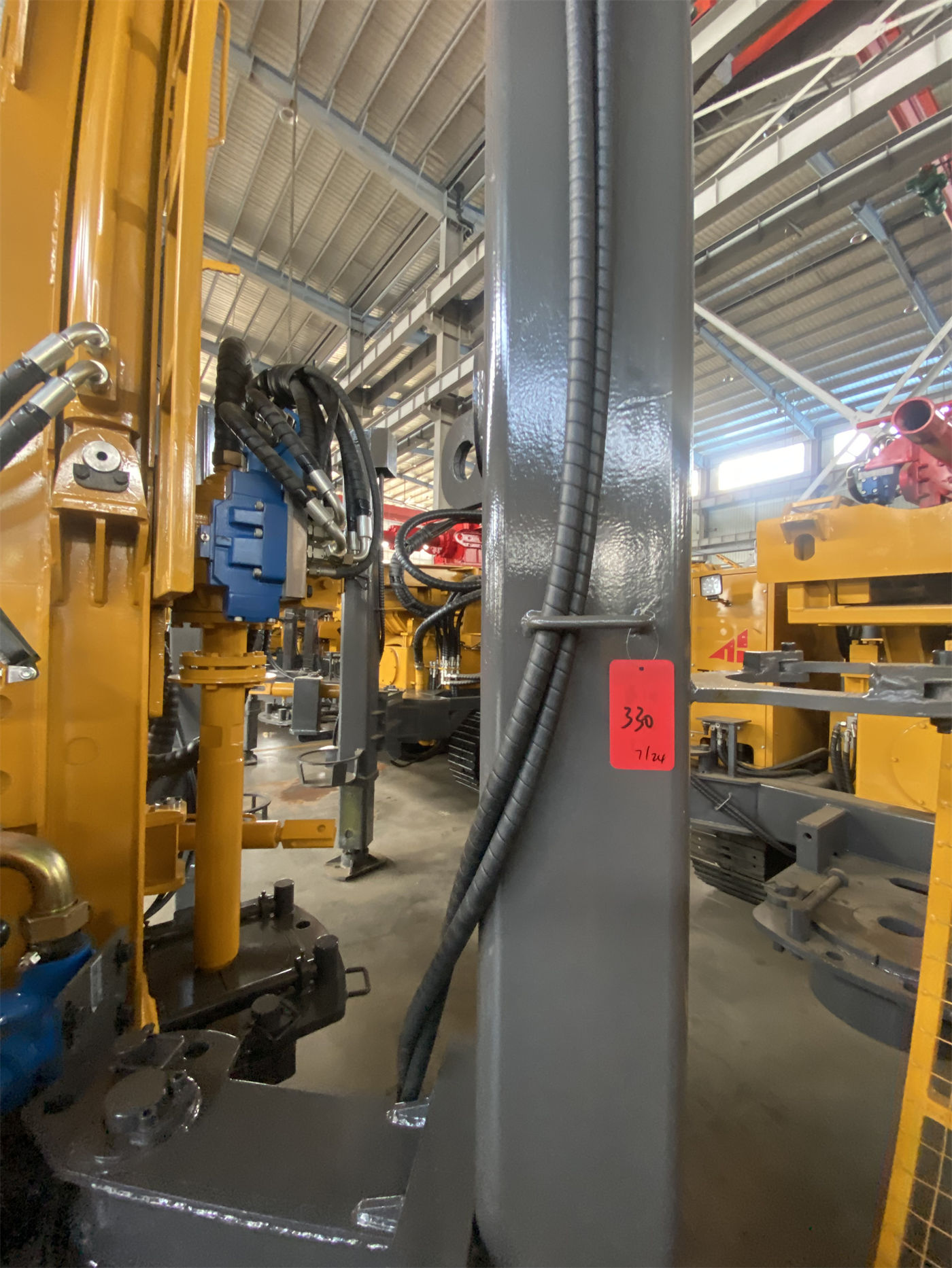
As hole depth increases, the self-weight of the drill pipe and the friction of the hole wall rise simultaneously. The materials' explanation for abnormal pull-out resistance is to first clean the hole, inspect the drill pipe, and judge the hole wall condition, rather than relying on the maximum lifting force to pull back forcibly. This is the handling direction explicitly stated in the materials.
Step 4: Power and pneumatic support determine whether the process can be switched
The 91 kW power system must simultaneously supply hydraulic rotation, feed, crawler travel, and auxiliary actions; it is not an independent value serving only drilling. Whether the power margin is sufficient during larger hole diameters, hard rock, and continuous construction must be judged from the perspective of overall machine load distribution; the materials do not provide a detailed power distribution for each action.
When switching to DTH hammer drilling, the recommended working air pressure is 1.2–3.5 MPa, air consumption is 16–55 m³/min, and medium- and high-pressure DTH hammers can be used. The materials' requirement for air compressor selection is to combine hole diameter, drill pipe, DTH hammer specification, rock hardness, and construction altitude, and point out that insufficient air volume will cause poor cuttings removal, while excessive configuration will increase equipment and fuel costs. In other words, the air compressor cannot be selected only according to the machine's maximum working pressure, but must be back-calculated from the project's hole diameter and DTH hammer specification.
Optional configurations include mud pump, centrifugal pump, generator, and foam pump. The selection approach given in the materials is to choose according to working conditions: projects with more loose layers pay more attention to the mud system, hard rock projects pay more attention to the air compressor and DTH hammer, and projects lacking a stable power supply may need a generator. The foam pump is an optional configuration used for some pneumatic drilling and treatment of air-leakage formations.
Step 5: Site, relocation, and pre-start inspection
The overall machine weight is about 7.5 T, dimensions are about 5.78 × 1.7 × 2.25 m, crawler travel speed is about 2.5 km/h, maximum climbing angle reference is 21°, hydraulic outrigger stroke is 1.5 m, and auxiliary winch lifting force is 1.1 T or 2.5 T optional. These values determine whether it can enter the site, whether it can be leveled, and whether auxiliary operations are sufficient.
- Before relocation, the working mechanism should be retracted, and slope and ground bearing capacity should be assessed; travel risks should be reduced on wet and slippery roads and soft soil areas.
- Soft ground needs pads before using outriggers for leveling, to avoid settlement during construction affecting hole deviation and mast stability.
- For projects with many casing, DTH hammer, or lifting needs, the auxiliary winch can be selected with a larger capacity configuration according to actual conditions.
The daily inspection items listed in the materials include the hydraulic system, rotary head, crawler, outriggers, drill pipe, and high-pressure air hose; during DTH drilling, check DTH hammer lubrication and air compressor status; during mud drilling, pay attention to whether circulation is smooth; after construction, clean mud, dust, and rock powder, and inspect drill pipe threads, hydraulic joints, and wear parts.
Several outcomes after checking in order
After completing the five steps above, one usually falls into one of three situations: the hole depth, hole diameter, and well completion structure all fall within the publicly stated capability range of the WR350SE, and the drill pipe, lifting force, and pneumatic support all match; or the hole depth is within range but the final hole diameter is on the large side, the overburden is thick, and the expected downhole resistance is high, requiring the margin of lifting force and torque to be separately checked; or the project's requirements for casing, lifting, or air compressor exceed the description in the materials, requiring confirmation with the manufacturer before judgment.
The materials themselves do not give the correspondence between different hole diameters, different formations, and achievable depths, nor do they give a recommended air compressor model list or casing specification table. These items are not covered by the materials and need to be confirmed in writing during the inquiry stage. The materials also state at the end: due to differences in actual geological conditions, downhole tools, drilling angle, and operating methods, the final drilling efficiency, drilling depth, and well completion effect should be based on on-site working conditions.