












Preparing a telescopic mast water well drilling rig is not entirely the same as preparing a standard straight mast model. The mast can be shortened for transport, but it must be extended again for operation; 6-meter drill pipes can reduce the number of connections, but the pipe length and casing specifications must be determined before mobilization. Using the publicly available WR400S specifications from this site as a sample, this article lists the conditions that can be determined from the documentation before mobilizing this 400-meter-class telescopic mast crawler water well drilling rig, item by item according to the steps that need to be settled first, and separately identifies the parts not covered by the documentation.
First Define the Hole Itself: Hole Depth, Hole Diameter, and Final Hole Structure
The WR400S documentation states a maximum drilling depth of 400 m and a drilling diameter of 105–325 mm. These two figures are the equipment capability range. What really needs to be put on paper before mobilization is the target hole depth, final hole diameter, and well casing structure for the well this equipment will drill. The target hole depth corresponds to local hydrogeological conditions; the documentation itself cannot judge the aquifer location for the project, nor can it infer that a certain area can definitely be drilled to a certain depth.
- Target hole depth: 400 m is the equipment upper limit; the actual final depth is determined according to local hydrogeological data
- Final hole diameter: take a value within the 105–325 mm range, and determine it together with the well casing and screen pipe diameters first
- Opening hole diameter: whether to start with a larger diameter first; the documentation does not list an opening structure plan, so it must be confirmed separately according to the well completion design
Then Define Drill Pipe and Casing: The 6-Meter Specification Affects More Than the Number of Connections
The WR400S supports direct operation with 6 m drill pipes and 6 m casings, with recommended drill pipe diameters of 89 / 102 mm. Before mobilization, it is necessary to confirm the actual drill pipe length, diameter, and casing specifications purchased for the project, as well as the on-site storage, handling, and lifting point positions for pipe loading.
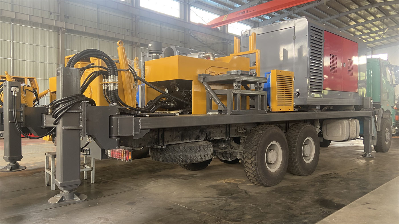
- Drill pipe: 6 m pipe length and recommended diameters of 89 / 102 mm; the actual pipe diameter used is determined by the project
- Casing: 6 m casing can be used directly; casing diameter, wall thickness, and connection type must be confirmed according to the well completion design
- Auxiliary winch: the documentation states a lifting force of 1.5 T, which can be used for handling DTH hammers, drill pipes, and casing tools; on site it must be matched with reasonable lifting points and manual guidance
If only 3 m pipes are actually used, the number of connections will increase, and auxiliary time will also change; this item belongs to construction organization, and the documentation does not provide time-saving figures, so no calculation is made.
Clarify the Process Route in Advance: What the Mud Section and DTH Hammer Section Each Require
The WR400S documentation also states support for both mud drilling and DTH hammer drilling. Determining the formation sections and corresponding processes before mobilization makes it easier to arrange support than switching processes on site.
| Hole Section | Possible Process | Support to Be Confirmed Before Mobilization |
|---|---|---|
| Loose overburden such as soil, clay, and sand layers | Mud drilling | Mud pump, mud materials, circulation and mud storage conditions (listed as optional configuration in the documentation) |
| Competent rock formations | DTH hammer | Air compressor, DTH hammer, drill bit, lubrication |
| Weathered rock, alternating soft and hard | Switch according to hole section | Both process supports must be prepared; pay attention to block falling and hole shrinkage |
| Fracture zones, fissures, air leakage formations | Documentation indicates possible use of foam or casing | Foam pump (optional configuration), casing, and corresponding hole cleaning arrangements |
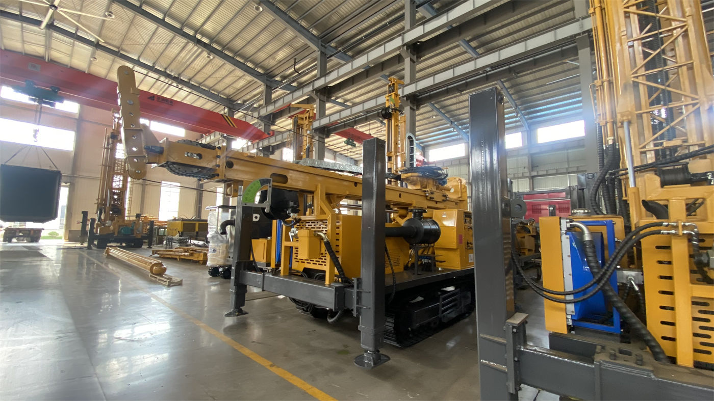
It should be noted that the documentation states recommended working air pressure of 1.2–3.5 MPa and air consumption of 16–55 m³/min for pneumatic conditions. These two figures must be considered together: selecting an air compressor based only on pressure without looking at displacement can easily cause problems in hard rock or large-diameter sections. How air compressor capability changes under high-altitude conditions is not covered by the documentation and must be verified separately.
Water and Power Supply Must Be in Place Before Mobilization
The documentation does not state the water consumption or on-site power supply requirements for the WR400S, so this part can only be confirmed according to actual optional equipment and site conditions, and cannot be inferred from the main machine parameters.
- Water use: mud drilling and well completion operations require on-site water sources and water storage conditions; the specific amount is calculated according to the process and hole diameter
- Power supply: if on-site lighting, auxiliary electric equipment, or domestic electricity is needed, arrangements must be made in advance; the documentation does not list external power supply parameters for the complete machine
- Optional items: mud pump, centrifugal pump, generator, and foam pump are optional configurations and must be confirmed together when ordering to avoid missing support upon arrival
Site and Relocation: The Boundaries of the Crawler Chassis Must Also Be Confirmed First
The WR400S has a crawler chassis. The documentation states a travel speed of about 2.5 km/h and a maximum climbing angle reference of 21°. The telescopic mast can shorten the overall machine profile in transport condition, which is a practical convenience for construction teams that need frequent loading and relocation, but it does not mean site condition problems disappear.
- The complete machine weighs about 9.8 T, with overall dimensions of about 6.26 × 1.85 × 2.43 m; estimate the vehicle and loading method accordingly before transport
- Ground bearing capacity, slope, and wet or slippery conditions along the travel route must be verified on site to avoid heavy equipment sinking into soft ground
- The mast should be in a safe transport state during relocation; the locking structure and equipment fixing points must be checked
- Drill pipes are recommended to be bundled and transported separately, not placed randomly with the machine body
The documentation does not list transport approval, road height or width restrictions, or lifting plans; such content must be arranged separately according to the project location and carrier requirements.
Check These Points First Upon Mobilization
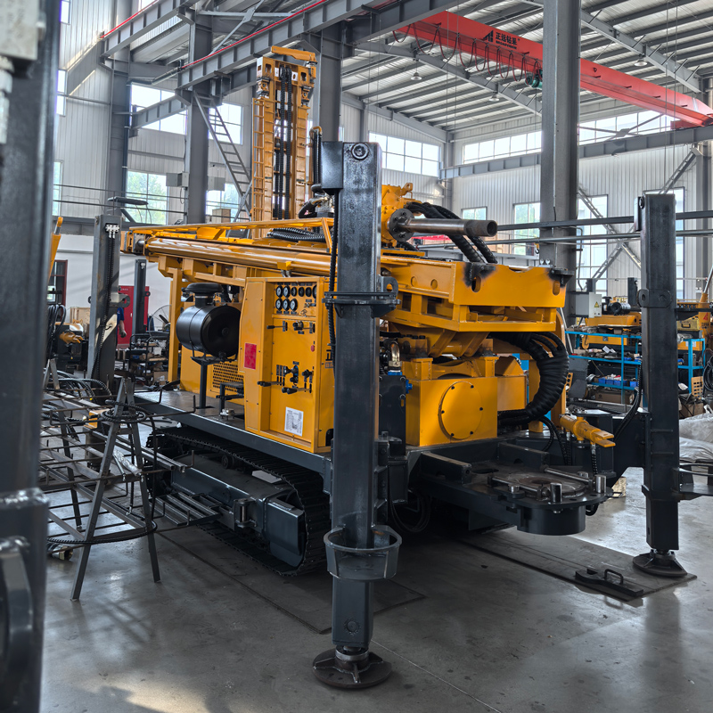
In addition to routine checks such as engine cooling, air filter, hydraulic oil temperature, tracks, outriggers, and drilling tools, the WR400S as a telescopic mast model has several structure-specific points.
- Telescopic mast guide rails: check for abnormal wear, deformation, or foreign objects
- Telescopic hydraulic cylinders and pins: check connections, fastening, and leakage
- Locking structure: confirm whether the transport state and working state locks are in place
- Hydraulic outriggers: stroke 1.6 m; use pads on soft ground and ensure even force distribution
- Engine: 92 kW Yuchai power; on dusty sites, increase the frequency of radiator and filter cleaning
Matters Not Covered by the Documentation That Still Need Separate Confirmation Before Mobilization
- The basis for determining the target hole depth and final hole diameter for the specific project
- Design of well casing, screen pipe, and water stop section for well completion
- Actual selection of air compressor under high-altitude or high-temperature environments
- On-site water source and power supply conditions
- Transport approval, lifting operation plan, and on-site safe operation procedures
- Training, random spare parts, and consumable spare parts stocking list
The above items have no corresponding content in the publicly available WR400S documentation on this site. They are parts that must be confirmed item by item with the project owner and manufacturer before mobilization and are outside the scope of inference from the documentation.