












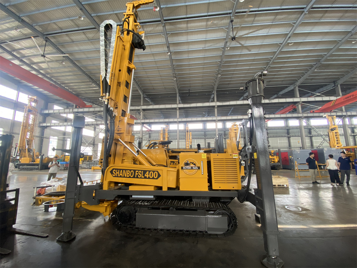
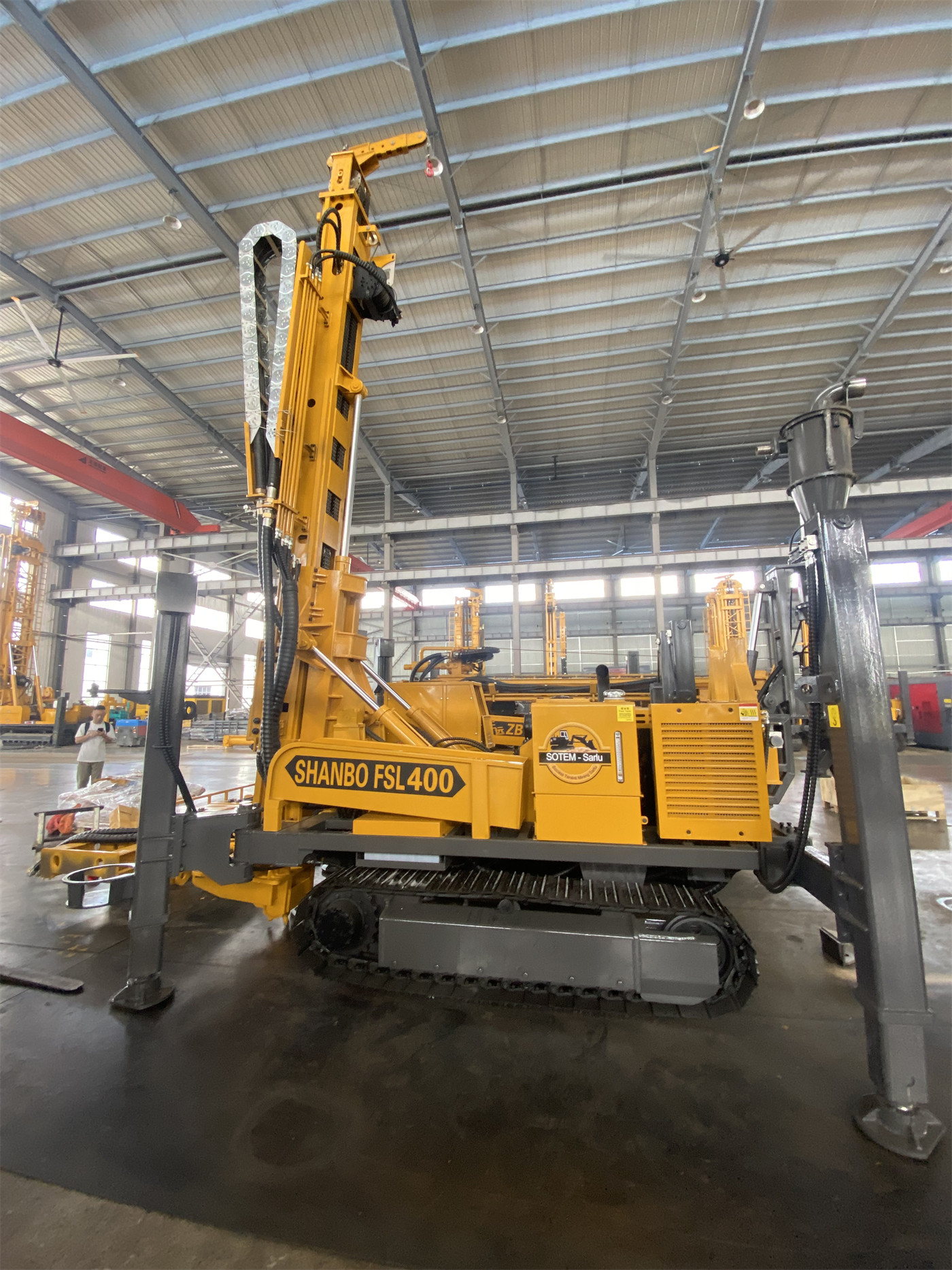
There is a key limitation in the equipment description of the WR400RC: it obtains cuttings samples returned by depth, not continuous intact cores. This statement determines that "equipping cuttings sampling or continuous coring" is not an accessory choice—the reverse circulation drill rig itself does not provide continuous coring functionality. The truly available routes are: use the WR400RC for RC cuttings sampling, or assign continuous coring to another type of core drill rig.
Reversing the order makes it clearer: first clarify the geological questions the project needs to answer, then determine whether the sample form can support that answer, and finally check whether the WR400RC's hole diameter, drilling depth, and supporting conditions are sufficient. The following expands on four judgment paths. Where numerical values can be written, they are stated clearly; parts not covered by the data are marked separately as to be confirmed.
Path 1: First Look at What Geological Questions the Samples Need to Answer
RC sampling yields a collection of cuttings from a footage interval. It can reflect trends in color, lithology, alteration, and mineralization with depth, and can be collected at fixed footage intervals and sent to the laboratory for grade analysis. Suitable question types include: at what depth interval does the mineralization anomaly appear, roughly which side does the ore body boundary extend toward, and is it worth infilling the peripheral anomaly area.
Continuous cores answer another type of question: stratigraphic contact relationships, structural attitudes, and the specific mineral occurrence positions and textures. These two types of questions do not replace each other. If the project's goal is only to quickly verify a large anomaly area and establish more control points, the sample quantity advantage of RC cuttings is more obvious; if the decision must be based on core structural descriptions, then no matter how dense the RC sampling is, it cannot fill in this layer of information.
The application directions specified in the WR400RC data include mineral exploration, geological sampling, and deep water well construction. In gold projects, it can be used for surface anomaly verification, mineralization investigation below overburden, ore body boundary control, and peripheral extension drilling. The common feature of these uses is: samples are used for trend judgment, not for core-level structural description.
Path 2: Whether Physical Cores Need to Be Preserved
This layer of judgment is the most direct. Under the RC process, cuttings return to the surface through the inner tube of the dual-wall drill pipe. The particles are fragmented and mixed, and cannot be reconstructed into a continuous columnar core. If the project itself has core library requirements, physical samples that need long-term preservation and repeated observation, or the contract specifies core recovery rates, then this route cannot be satisfied from the process perspective. Continuous coring should be assigned to a core drill rig, rather than solved by adding configurations to the WR400RC.
Conversely, if the project only needs cuttings samples, the final deliverable of the samples is assay data, and the site numbers, weighs, and packages them at fixed hole depth intervals, then the reverse circulation channel and 89/102 mm RC drill rods of the WR400RC are the corresponding configuration for this purpose. RC drill rods are 3 m long and have a different structure from ordinary single-wall drill rods. It is necessary to ensure the sealing and reliable connection of the inner and outer channels, and regularly inspect the dual-wall drill pipe joints, seals, and inner tube wear to avoid air leakage and sample contamination.
Path 3: Whether 400 Meters, 105–305 mm Hole Diameter Match Actual Hole Conditions
The WR400RC has a maximum drilling depth of 400 m, a hole diameter of 105–305 mm, and supports 45° and 90° working angles. The data also states that actual drilling depth will be affected by hole diameter, drill rods, air compressor capacity, formation conditions, hole deviation, and drilling tool wear. Therefore, 400 m should be understood as a reference capability under typical configuration, not a fixed value achievable under any hole conditions.
The judgment sequence can be arranged as follows:
- Whether the target hole depth significantly exceeds 400 m, or is close to 400 m without leaving margin for hole deviation and drilling tool wear;
- Whether the designed hole diameter falls within 105–305 mm, and whether the air compressor capacity matches the target hole diameter and depth—the WR400RC recommends a working air pressure of 1.2–3.5 MPa and air consumption of 16–55 m³/min. When hole depth increases, hole diameter increases, or the rock formation is hard, insufficient air volume will directly cause the cuttings return speed to decrease;
- Whether the hole direction requires 45° inclined holes. The data gives two working angles, 45°/90°, which can be used for inclined holes or near-vertical holes, but the hole direction and hole angle should be confirmed according to the geological design before formal construction;
- Whether the upper loose overburden will use mud drilling for transition. Soil layers, clay, sand layers, and gravel layers are prone to hole collapse. The data indicates that this model supports mud drilling, which can first stabilize the hole and then switch to pneumatic or reverse circulation processes.
If the target hole depth far exceeds 400 m, or the designed hole diameter is greater than 305 mm, then this route itself does not hold, and it is necessary to re-compare the capability ranges of other models rather than adjust the sampling method.
Path 4: Whether On-Site Sampling and Splitting Capabilities Can Keep Up
Reverse circulation sampling is not just about "drilling fast"; it also requires ensuring that samples return continuously by depth. During construction, observe the sample return volume, particle size, dust changes, and whether there is obvious cross-contamination. Each time a rod is added, the hole is cleaned, or drilling is stopped and sampling restarts, the transition section should be handled according to the on-site sampling system to avoid mixing samples from different depths. Fault fracture zones are prone to block falling and local hole enlargement. Cuttings may stagnate in the hole and then return in a concentrated manner, causing the depth correspondence of samples to deteriorate. For such hole sections, control the advance speed, maintain stable air supply, and keep good records.
The WR400RC provides a drilling platform. The final sample quality also depends on the on-site sampling process and personnel operation. If the project party does not have a supporting sample numbering, weighing, packaging, and recording process, even if the equipment is selected correctly, the data quality may not meet standards. This item is as important as equipment selection.
Comparison of the Judgment Sequence of the Four Paths
| Judgment Path | Conditions Favoring Cuttings Sampling | Conditions Pointing to Continuous Coring |
|---|---|---|
| Questions the samples need to answer | Anomaly verification, boundary control, trend judgment | Stratigraphic contact relationships, structural attitudes, mineral occurrence textures |
| Whether physical cores are preserved | Continuous columnar cores are not required; assay data is the deliverable | Core library or core recovery rate requirements; physical samples need long-term preservation |
| Hole depth and diameter | Hole depth within the 400 m reference range, hole diameter 105–305 mm | Hole depth significantly exceeds 400 m or hole diameter exceeds this range |
| On-site sample management | Has processes for numbering, weighing, packaging, and recording by depth | —— (This row's condition does not apply to continuous coring judgment) |
The third and fourth rows in the table are progressive rather than parallel: when hole depth and diameter do not hold, the subsequent items do not need to be judged; when hole depth and diameter hold but on-site sample management cannot keep up, the problem lies in the process rather than the equipment, and the process needs to be improved before scheduling production.

Supporting Parameters on the Equipment Side and Items Requiring Written Confirmation
If the project ultimately falls on the RC cuttings sampling route, the relevant capabilities given in the WR400RC data include: maximum drilling depth 400 m, hole diameter 105–305 mm, working angles 45°/90°, lifting force 22 T, axial pressure 6 T, rotary torque 8000/4000 N·m, corresponding maximum rotation speeds 75/150 r/min, recommended working air pressure 1.2–3.5 MPa, air consumption 16–55 m³/min, recommended RC drill rods 89/102 mm, length 3 m, crawler travel speed about 2.5 km/h, maximum climbing angle reference 21°, overall weight about 11 T, hydraulic outrigger stroke 1.6 m, auxiliary winch lifting force 1.5 T, 92 kW Yuchai engine. This model can also be used for deep water well construction in rural water supply, farmland irrigation, industrial water use, and mining area groundwater development. Water well construction does not necessarily require the RC sampling system throughout the entire process.
The following items have not been concluded in the existing data on this site and should be confirmed in writing with the manufacturer or project party before procurement or production scheduling:
- Under the target hole depth, whether the actual pressure and displacement of the supporting air compressor can stably fall within the ranges of 1.2–3.5 MPa and 16–55 m³/min;
- The specific specifications of the cyclone or splitting equipment, cleaning cycle, and the adapted sample interval division method;
- The hole direction control means and verification method for 45° inclined holes in the target formation;
- The conversion conditions for mud drilling and pneumatic RC within the same hole, the required casing specifications, and the conversion procedure;
- Which type of core drill rig will undertake the continuous coring requirement, and how the hole position connection and sample numbering of the two types of equipment will be unified.
By walking through these four paths in order, it is usually possible to determine which side the project belongs to. What is truly prone to problems is not the selection itself, but starting work directly when the hole depth and diameter hold but the on-site sampling process is not prepared, ultimately obtaining a batch of samples with unclear depth correspondence.