












During arrival acceptance of a water well drilling rig, what truly needs to be checked step by step is often not the overall appearance of the machine, but the rotary table, winch, hydraulic system, and mud pump. The reason is straightforward: these four items respectively correspond to rotation, tripping, motion transmission, and cuttings discharge circulation. Once problems are found after being put into use on site, the handling cost is far higher than checking at the unpacking stage. This article organizes the parts and actions to observe at each step in the natural order of acceptance, and also explains which items lack judgment values in the existing materials on this site—such items should be confirmed in the contract, factory documents, or written confirmation from the manufacturer before execution, and cannot be replaced with data from other models.
Before acceptance, place the three sets of documents together first
Before touching any component, it is recommended to first confirm that you have three sets of materials on hand: the configuration list in the procurement contract, the factory random documents provided by the supplier, and the actual packing list for this arrival. The three serve different purposes: the contract states "what should be included," the factory documents state "the condition and parameters given by the manufacturer," and the packing list states "what actually arrived." The rotary table, winch, hydraulic system, and mud pump often involve matched parts and random accessories, and cannot be fully checked based only on the machine nameplate.
It should be noted that the existing product materials on this site mainly cover model capabilities, structure, and application descriptions, and do not provide factory acceptance standards, pressure test values, oil cleanliness judgment values, or no-load running time requirements for each model of water well drilling rig. Therefore, the following can only provide a checklist of "what to check, what to look at, and what actions to perform." Specific pass/fail judgment values must be based on the manufacturer's documents.
Step 1: Rotary table—first check appearance and fixation, then perform no-load rotation
The rotary table is the core output component of the rotation system, and the acceptance sequence is recommended to go from static to dynamic.
- Appearance and cleanliness: Check the rotary table housing, oil sump, and upper cover plate for transportation impacts, signs of leakage, and foreign matter entry.
- Fixation status: Verify whether the connecting bolts between the rotary table and the frame or base are complete and whether tightening marks are intact.
- Lubrication and oil level: Confirm the lubricating oil grade and oil level range according to factory documents, and check whether they are within the normal range after transportation.
- Rotating body clearance: Manually turn or jog at low speed to feel for abnormal jamming, abnormal noise, or obvious play.
- No-load rotation: Without drilling tools installed, perform a trial run in the manner permitted by the manufacturer, and observe whether rotation is smooth and whether there is abnormal vibration or temperature rise.
- Auxiliary components: Check whether the rotary table's matching bushings, kelly bushings, and seals are complete according to the packing list.
The parameter limits and duration for no-load trial running of the rotary table are not covered in the materials on this site and should be executed according to the manufacturer's operation manual. If abnormal noise or oil leakage occurs during the trial run, it should be recorded and paused; it is not advisable to continue load testing.
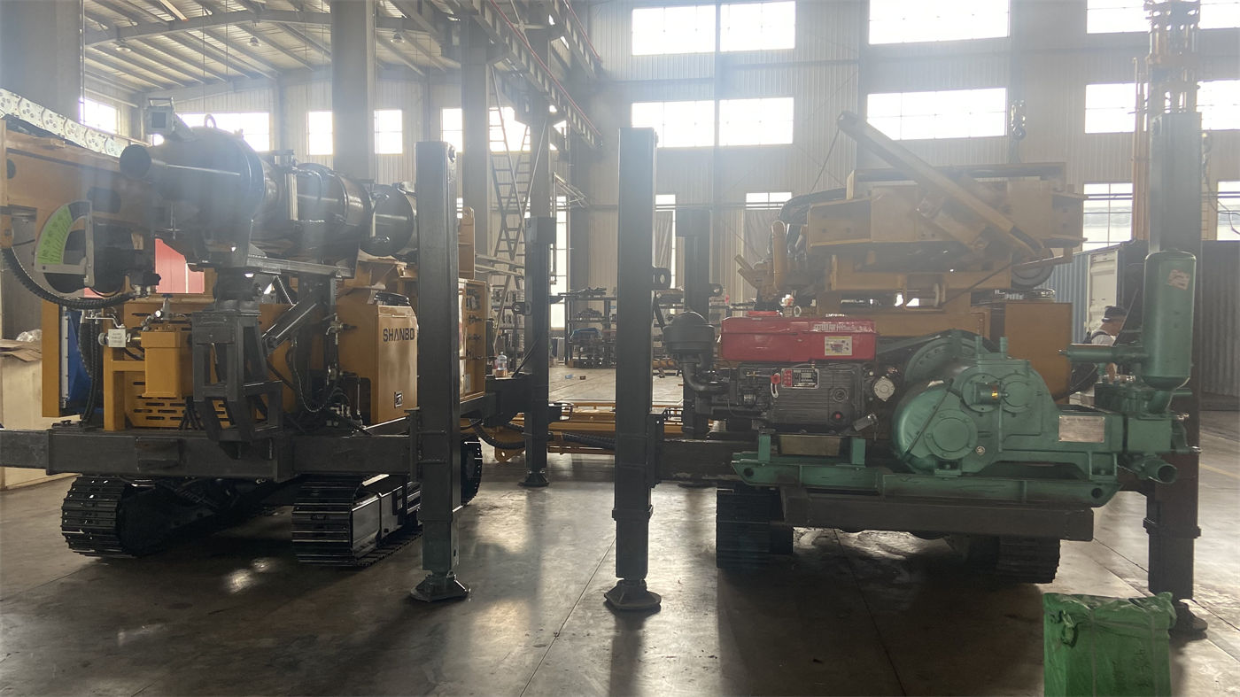
Step 2: Winch—braking and wire rope are key inspection points
The winch handles tripping and some casing operations. During acceptance, the focus is on three items: braking, drum, and wire rope.
- Braking system: Check whether the brake band or brake disc, brake cylinder, linkage, and springs are properly assembled. Manually or by jogging, confirm whether the braking action is reliable and whether there is jamming.
- Drum and spooling: Check the drum surface and rope grooves for impact damage, and whether the spooling mechanism operates smoothly.
- Wire rope: Check whether the specification, diameter, lay direction, rope end fixation method, and number of winding layers conform to factory documents; check for flattening, broken wires, corrosion, and other abnormalities caused by transportation.
- Clutch and control: Confirm that the action directions of the clutch, reversing, and operating handles are consistent with the markings, and that there is no abnormal travel.
- Safety devices: According to the contract and factory documents, check whether limit, anti-fall, or overwind protection devices are configured and operate normally.
The lifting force values appearing in the product materials on this site (for example, the 22 T lifting force of WR400RC, the 15 T lifting force of WR260, the 30 T lifting force of WR500S, etc.) are nominal capability descriptions for the corresponding models and cannot be directly used as load judgment values for winch acceptance. The test lifting load, brake slip amount, and wire rope scrapping standards during acceptance should be based on the manufacturer's documents and corresponding safety regulations.
Step 3: Hydraulic system—check leakage and pressure in oil circuit order
The hydraulic system covers rotation, feed, travel, outriggers, and auxiliary actions. During acceptance, it is recommended to proceed in the order of "oil—hoses—valves—cylinders—gauges."
- Oil: Verify the grade, oil level, and appearance; check whether the oil tank breather and filter elements are in place according to the packing list.
- Pipes and fittings: Inspect each hose for squeezing or abrasion, each fitting for leakage, and whether pipe clamps are loose.
- Valve groups and pumps: Confirm that the model markings of each valve group, pump, and motor match the contract configuration, and that there is no impact damage on the surface.
- Cylinders and outriggers: Check the piston rod surface for scratches, and whether the hydraulic outriggers operate synchronously and reach position.
- Pressure gauges and sensors: Confirm that pressure displays, temperature displays, and other indicating components are installed and have normal readings.
- No-load actions: According to the sequence permitted by the manufacturer, jog each actuator one by one, and observe for creeping, abnormal noise, leakage, and abnormal temperature rise.
System working pressure, flow rate, oil cleanliness level, and trial run time are not provided in the materials on this site and must be based on the manufacturer's materials. If testing conditions are already available on site, pressure measurement and oil sampling should be carried out at the interfaces and under the conditions confirmed by the manufacturer.
Step 4: Mud pump—check matching first, then check actions
Acceptance of the mud pump is easily simplified to "whether it can turn." In fact, it should be checked at two levels.
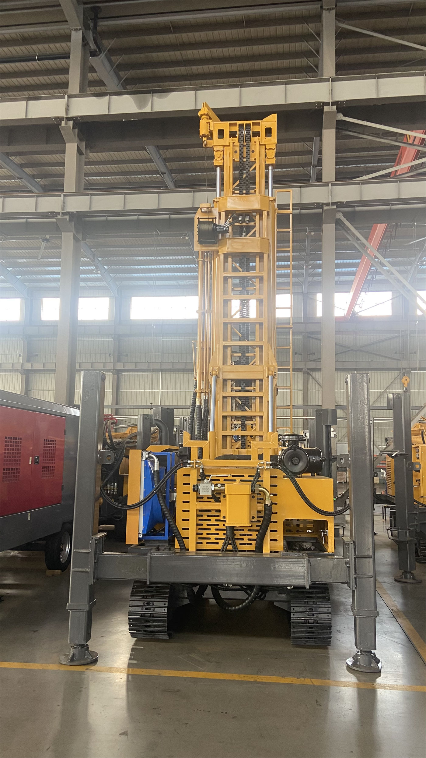
- Model and configuration: Confirm that the pump model, number of cylinders, and transmission mode match the contract; existing materials have included a configuration description of a trailer-mounted rotary table drilling rig WRTR600 equipped with a 3NB-130 mud pump, but different models have different matching pumps, and other projects must be based on their own contracts.
- Accessory completeness: Check whether random parts such as the suction hose, discharge hose, valve cover, valve seat, cylinder liner, piston, seals, safety valve, and pressure gauge are complete.
- Appearance and lubrication: Check the pump body and crankcase for leakage, and whether the lubricating oil level conforms to factory documents.
- Action check: Under no-load or clean water conditions, jog in the manner permitted by the manufacturer, and observe whether the reciprocating action is smooth and whether there is abnormal noise or abnormal heating.
- Pipeline connection: Check the connection direction and fixation of suction and discharge pipelines, and confirm that the safety valve discharge direction is clear and not facing personnel passage areas.
The rated pressure, displacement, stroke rate, and corresponding trial run procedures of the mud pump must be based on factory documents; the pump matching models appearing in the materials on this site are only used to illustrate that "different machine models have different matching configurations" and do not constitute a basis for acceptance judgment.
Acceptance sequence and recording suggestions
To link the four inspections together, refer to the following sequence and recording items. The "confirmation basis" listed in the table refers to materials that need to be obtained from the manufacturer on site, rather than values that can be directly provided by the materials on this site.
| Sequence | Inspection object | Main actions | Judgment basis to confirm with the manufacturer |
|---|---|---|---|
| 1 | Documents and packing | Compare the contract list, factory documents, and packing list | Random accessories and training service scope (should already be specified in the contract) |
| 2 | Rotary table | Appearance, fixation, oil level, manual turning, no-load rotation | Lubricating oil grade, no-load trial run procedure, allowable temperature rise |
| 3 | Winch | Braking, drum, wire rope, clutch, safety devices | Test lifting load, braking judgment standard, wire rope specification and scrapping standard |
| 4 | Hydraulic system | Oil, pipes, valves and pumps, cylinders, pressure display, no-load actions | Working pressure, flow rate, oil cleanliness, and pressure test procedure |
| 5 | Mud pump | Model configuration, random accessories, lubrication, no-load actions, pipeline routing | Rated pressure and displacement, trial run procedure, safety valve setting value |
For each step, it is recommended to record simultaneously: inspection time, participating personnel, observed phenomena, abnormal parts found, and handling methods. If an item cannot be verified on the spot due to lack of conditions, it should be written as "to be confirmed" in the record, rather than left blank or assumed to be qualified.
Which items cannot be given judgment bases by the materials on this site
To avoid treating capability descriptions as acceptance standards, the following matters need separate explanation:
- The time, speed, pressure, and temperature limits for various trial runs are not covered in the materials on this site and cannot be derived from model parameters.
- The cleanliness level and replacement cycle of hydraulic oil and lubricating oil need to be determined according to the manufacturer's manual and on-site environment.
- The test lifting load and safety factor of the wire rope and lifting system should be based on the corresponding safety regulations and cannot be applied from the nominal lifting force.
- The pass/fail judgment values for mud pump pressure and displacement must be based on factory documents.
- The acceptance methods for electrical, control, and safety protection devices are not provided in the materials on this site and should be confirmed separately.
It should be emphasized that the inspection steps listed in this article come from an organization of the common component functions of drilling rigs, and are intended to help purchasers form an acceptance approach; specific judgment values, test methods, and safety requirements must be provided in writing by the supplier and confirmed on site before execution.