












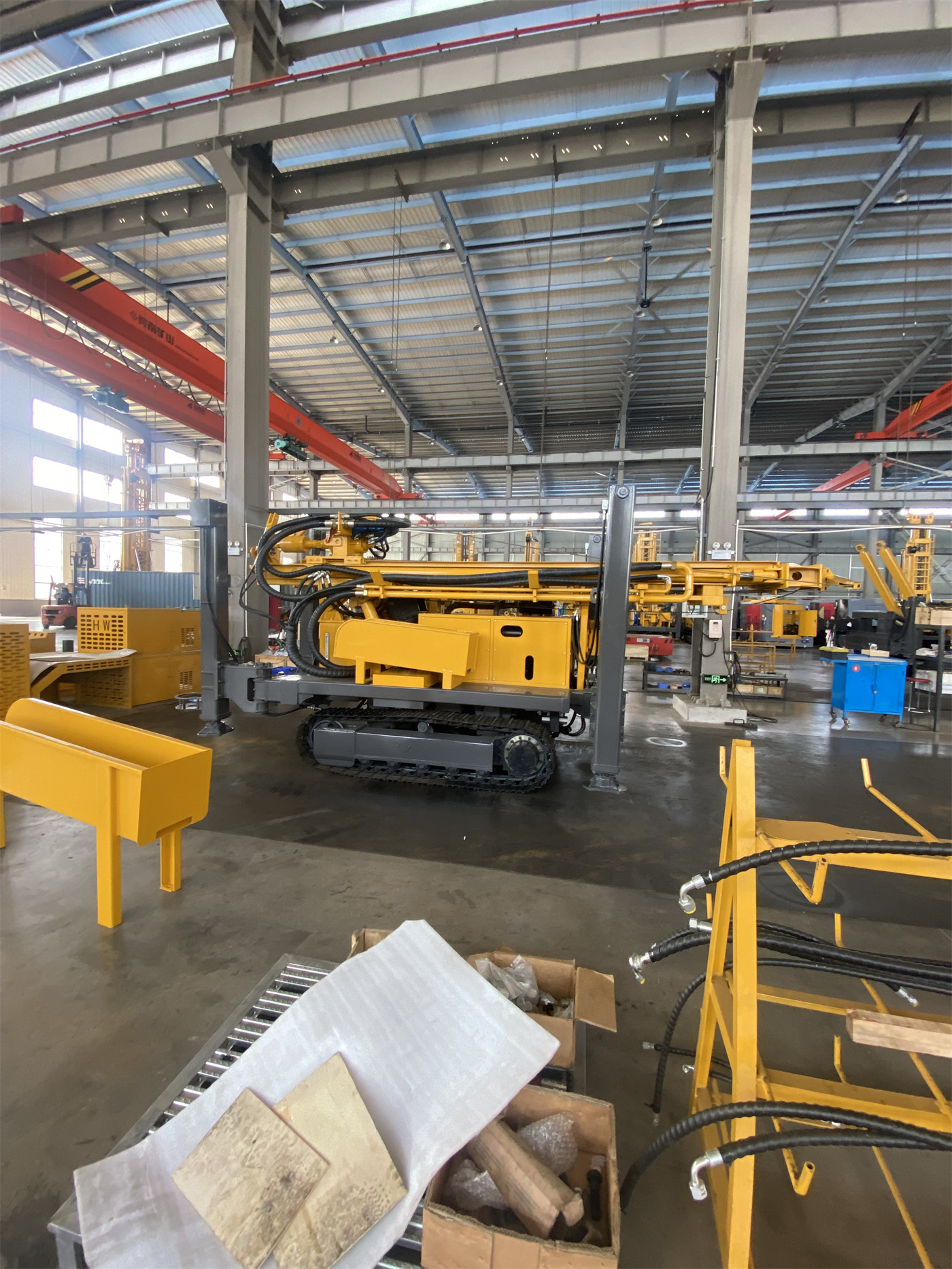
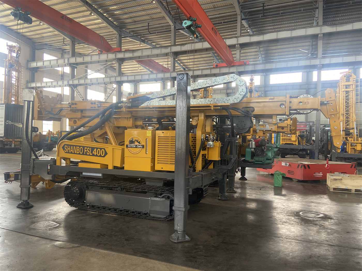
Treating a 600-meter-class reverse circulation drill rig as a single capability level makes it easy to overlook that it simultaneously handles three distinct tasks: the first is drilling holes to the 600 m range, the second is forming holes within a diameter range of 105–450 mm, and the third is returning cuttings to the surface by depth using an inner-tube reverse circulation method. These three tasks coexist on the same machine, but the constraints behind each are different, and the relationship between them is not simply "the larger the parameter, the better." Using the published information on the WR600RC as a guide, let us examine these three tasks separately.
Task One: Which Sets of Values Together Support Deep-Hole Capability
The maximum drilling depth given in the WR600RC information is 600 m. This value is qualified in the information as "reference capability under typical configuration," meaning it is not a fixed value achievable under any hole diameter, any drill pipe combination, or any formation. Alongside drilling depth in the same document are several other sets of values supporting deep-hole operations: lifting force 29 T, rotary torque 12000 / 6000 N·m, corresponding maximum rotary speeds 75 / 150 r/min, working air pressure 1.6–6 MPa, and air consumption 16–75 m³/min.
The first requirement deep holes place on equipment appears during tripping. As hole depth increases, the self-weight of the dual-wall RC drill pipe and the friction against the hole wall both rise; the 29 T lifting force serves as drill string handling capacity along this path. The information also notes that if pulling resistance remains abnormal, the priority should be to handle it through hole cleaning and assessing downhole conditions, rather than directly pulling with maximum lifting force. This statement characterizes lifting force as an operational capability, not a means of resolving downhole problems.
The second requirement appears along the sample return path. 600-meter-class RC drilling must send cuttings back to the surface through the inner tube; the deeper the hole, the longer this path, and the demand for air pressure and air volume typically increases. The information states working air pressure as 1.6–6 MPa and air consumption as 16–75 m³/min, and explicitly notes that as hole depth, hole diameter, altitude, and rock hardness increase, the required effective air volume typically also rises. These two sets of values are supporting conditions directly related to drilling depth, not options that can be discounted independently.
Deep-Hole Task Cannot Be Assessed by the Drilling Depth Number Alone
Extracting 600 m alone as a basis for comparison discards three layers of prerequisites: hole diameter, drill pipe specification, and whether the supporting air compressor can maintain sufficient effective air volume at that depth. The information itself does not provide a correspondence for "how much air volume is needed for 600 m at a specific hole diameter"; this part requires separate verification with the manufacturer or project party based on actual hole depth, hole diameter, and altitude.
Task Two: Which Operating Conditions Fall Within the 105–450 mm Hole Diameter Range
The information does not define the 105–450 mm hole diameter range as serving a single purpose. Three categories of application appear alongside this range: mineral exploration holes, deep water well construction, and dewatering holes in some mining areas. The three categories focus on different aspects of hole diameter—exploration holes focus on the sample return channel and sample representativeness, water wells focus on well completion structure and aquifers, and dewatering holes focus on well location, well spacing, and hydrogeological design.
Under the RC process, there is a direct relationship between hole diameter and sample return conditions. The larger the hole diameter, the greater the volume of cuttings that must be discharged per unit time; the deeper the hole, the longer the return path. When these two directions combine, the demand for air pressure and air volume rises simultaneously. The air consumption range given in the information (16–75 m³/min) covers a fairly wide span; where it actually falls depends on the specific combination of hole diameter, hole depth, and rock formation conditions. The information does not provide an item-by-item correspondence table.
Under non-RC conditions, the 105–450 mm range also corresponds to two methods: mud rotary and conventional DTH hammer drilling. The information states that the equipment supports these two methods and gives two typical use scenarios: for loose overburden (soil, sand, gravel), mud rotary can first be used to stabilize and form the hole, then switch to RC or DTH upon entering stable rock; for more intact rock (granite, limestone, sandstone, etc.), whether RC or ordinary DTH is used can be decided based on whether geological samples are needed. This shows that the hole diameter range itself is not the condition for process selection; process selection depends on formation and sampling requirements.
What the Hole Diameter Task Changes
Adjusting the hole diameter from 105 mm to 450 mm changes first the total volume of cuttings to be handled and the sample return channel conditions, and only secondarily the purpose of the hole itself. This means hole diameter selection cannot look only at "whether the hole needs to be this large," but must also consider whether the supporting air compressor, drill pipe, and sample return system can maintain stable sample return at this diameter.
Task Three: Sampling Method Is the Task Objective, Not Just a Process Name
In the WR600RC information, "reverse circulation" is first described as a sample return path: using dual-wall drill pipe, compressed air travels down the outer channel of the drill pipe, drives the RC hammer and bit at the hole bottom, and then carries cuttings back to the surface through the inner channel. Comparing this path with ordinary outer annulus discharge, the information notes that the inner-tube return path is more concentrated, which helps reduce contact between samples and different hole sections and improves the operability of depth-segmented sampling.
The core of this task is not penetration rate but the correspondence between sample and depth. The RC method obtains cuttings samples, not continuous intact core. The information describes its applicable scenarios as follows: suitable for rapidly establishing a large number of drill hole control points, with synchronous sample return during drilling, making it convenient to record lithology, alteration, and mineralization changes at fixed footage intervals on site, and then send representative samples to the laboratory for assay. Therefore, sampling quality depends on two things being true at the same time—continuous sample return and synchronous depth recording.
The observation items given in the information for abnormal sample return include: changes in return volume, particle size, color, and moisture. If there is a sudden decrease in sample, delayed return, or obvious cross-contamination, check the drill pipe seals, sample return channel, air compressor output, and whether there is air leakage in the hole. This passage essentially states that the reliability of the reverse circulation sampling method does not rest entirely with the drill rig itself; drill pipe seals, air compressor output, and downhole conditions are all on the same chain.
What Supporting Elements the Sampling Method Requires to Be Synchronized
If the WR600RC is used for mineral sampling, then collecting samples at fixed footage intervals, recording hole number and start/end depths, and setting duplicate samples, standard samples, and blank samples according to the project quality control system are tasks separate from the drill rig parameters. The information explicitly states that "the drill rig is responsible for obtaining samples, and final data quality also depends on sampling management." This is a boundary statement for the sampling method task.

Linkages Among the Three Tasks
Putting the three tasks together shows that they are not independent of one another.
| Task | Relevant Values in the Information | Parts That Cannot Be Inferred Independently |
|---|---|---|
| Deep hole | Maximum drilling depth 600 m, lifting force 29 T | Actual achievable depth under specific hole diameter and formation |
| Hole diameter | 105–450 mm | Sample return air volume requirements for each hole diameter |
| Sampling method | Dual-wall drill pipe, inner-tube sample return | Specific sample splitting precision and sample contamination control indicators |
From the table it can be seen that: 600 m drilling depth corresponds to the supporting conditions of lifting force and air pressure/volume; 105–450 mm hole diameter corresponds to the combination of sample return capability and process method; and sampling method corresponds to drill pipe structure and on-site record management. The common constraint point of the three tasks is air pressure and air volume—when hole depth increases, hole diameter increases, or requirements for sample return continuity rise, the demand for this item is pushed higher.
Two other conditions span the three tasks: first, working angle. The WR600RC supports two angles, 45° and 90°, corresponding respectively in the information to inclined crossing of inclined ore bodies, veins, and fault zones, and to conventional vertical exploration and water well construction. Second, the overall weight is approximately 12.5 T and dimensions approximately 7 × 2.1 × 2.9 m. This item is not directly related to any of the three tasks, but it affects drill pad size planning, especially when an RC project also requires an air compressor, sample return hose, and sampling device.
Parts Not Covered by the Information That Require Separate Confirmation
- For a specific hole diameter, what size air compressor displacement is needed to support 600 m drilling depth. The information only gives an air consumption range, with no diameter-by-diameter correspondence.
- Within the 105–450 mm range, the actual penetration efficiency of a given diameter in a given formation is not provided in the information.
- During inner-tube sample return, specific values for sample cross-contamination control between different hole sections are not provided in the information.
- Hole deviation control requirements for a 45° inclined hole at 600 m depth are not provided in the information.
- The 3.5 km/h travel speed and 21° maximum climbing angle are reference values; actual site transfers also require confirmation of road load-bearing capacity and site stability.
Once the division of labor among the three tasks is clear, the discussion of a 600-meter-class reverse circulation drill rig can shift from "how deep can it drill" to "at what hole diameter and under what sample return requirements can it drill how deep." The latter is the question that must first be put on paper during equipment selection.