












The CR600I is a 600m-class fully hydraulic integrated crawler-mounted core drill rig. According to the information on this site, its BQ/NQ/HQ reference drilling depths are BQ 800 m, NQ 600 m, and HQ 300 m, with a drilling angle of 45°–90°, a maximum power head torque of 960 N·m, a folding mast, a feed stroke of 1.9 m, and a wireline hoist rope capacity of 800 m. Regarding the question of "how to calculate efficiency for folding mast and crawler mobility in mountainous multi-hole projects," one should not look only at a single drilling depth figure, but compare mobility time, auxiliary time, and in-hole operation time under the same criteria. The following content is organized based on verified product information on this site and does not involve unconfirmed customer cases or on-site measured data.
I. First Clarify the Configuration Boundaries of the CR600I
In the CR600I model designation, CR stands for core drill rig, 600 stands for N-size reference drilling depth of 600 m, and I stands for integrated structure. This site also lists BQ 800 m and HQ 300 m as reference drilling depths, indicating that the same equipment has different capabilities under different drill rod and coring system specifications. The actual achievable drilling depth is also affected by factors such as drilling angle, rock integrity, drill rod weight, in-hole tools, mud performance, borehole wall stability, and operating methods. Therefore, in procurement communication, one should avoid treating the reference value of a certain specification directly as a guaranteed value for all working conditions.
Structurally, the CR600I integrates the power system, hydraulic system, power head, mast and feed mechanism, clamp, wireline hoist, mud circulation system, and crawler travel mechanism on the same platform. This structural approach is the same as the CR800I available on this site, both being "I" series integrated core drill rigs, but they are not the same model, and their parameters cannot be substituted for each other. For mountainous multi-hole projects, the main value of the integrated design is reducing the workload of on-site assembly and repeated connections of split equipment, rather than replacing judgment on roads, platforms, and formation conditions.
II. Calculable Changes Brought by the Folding Mast
The CR600I mast adopts a folding structure, with a feed stroke of 1.9 m, capable of handling 1.5 m drill rods. The feed speed supports fast and slow adjustment, with a feed force of 42 kN and a pull force of 130 kN. In procurement discussions, a folding mast usually corresponds to a reduction in transport height and difficulty of mobility, but this site does not provide specific transport dimensions before and after folding, so it cannot be directly converted into "how narrow a road it can pass" or "how many hours it can save."
What can be calculated is the time related to drill rod length: with a feed stroke of 1.9 m and handling 1.5 m drill rods, there is a fixed relationship between a single feed stroke and the length of one drill rod. In a hole with an N-size 600 m reference drilling depth, estimated with 1.5 m drill rods, the theoretical number of rod additions is directly related to hole depth; the more holes, the higher the proportion of cumulative auxiliary time for rod handling, rod addition, coring, and collar operations. Whether the folding mast truly improves efficiency depends on whether the project can organize hole spacing, number of platforms, and relocation routes into continuous operation.
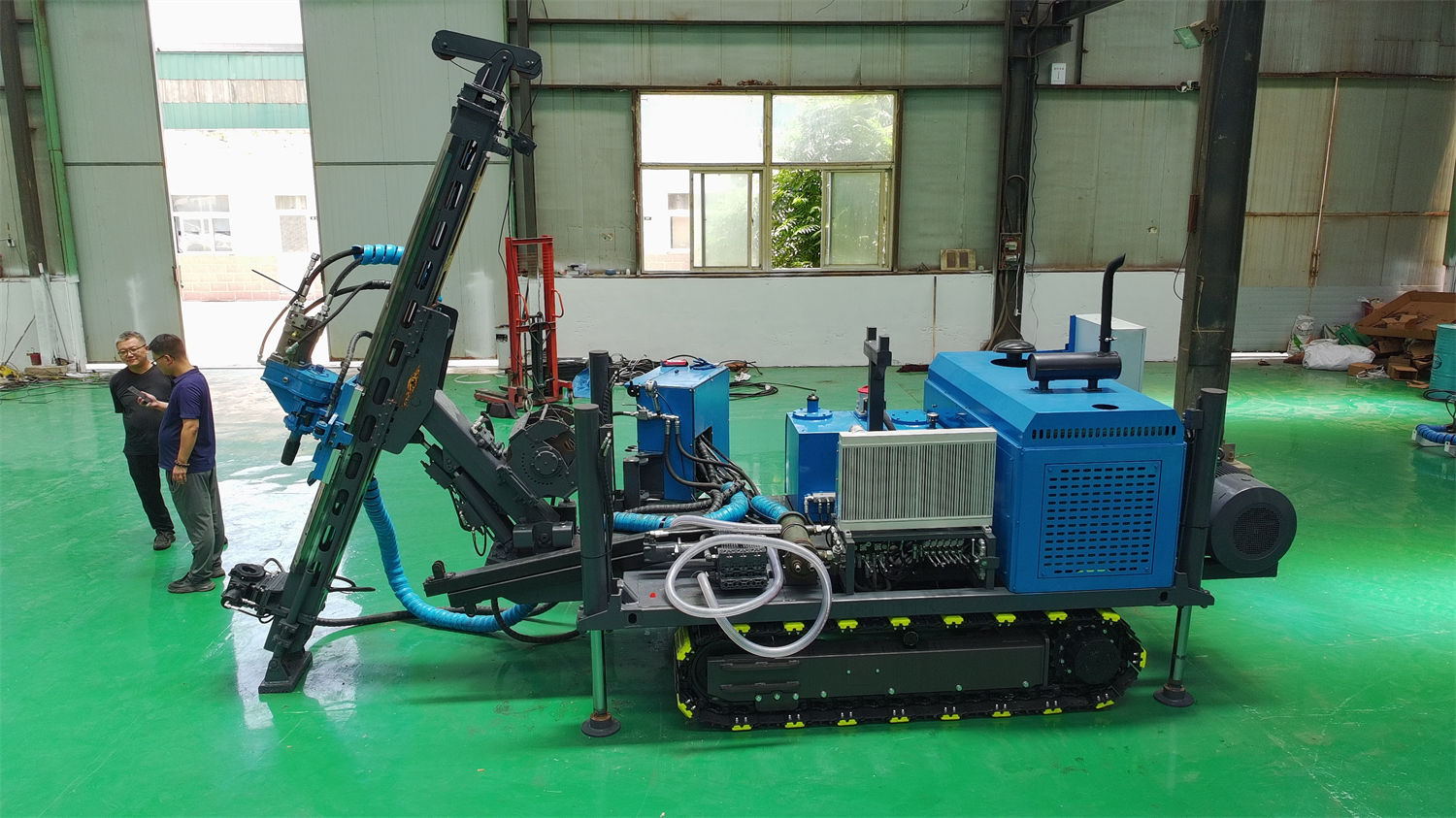
Mast Items Recommended to Verify with the Manufacturer Before Procurement
- What are the overall heights in folded and working states, and whether partial components need to be disassembled during transport.
- Which actions complete mast folding and unfolding, and whether they are included in the operable range of wireless remote control.
- The sequence between 45°–90° angle adjustment and folding actions, required site clearance, and auxiliary support conditions.
- The drill rod length matched with the 1.9 m feed stroke, rod addition method, and in-situ operating space.
III. What Items Should Be Included in Efficiency Calculation for Crawler Mobility
The CR600I uses a crawler chassis. This site's description of its applicable scenarios includes mining access roads, mountains, hills, gravel roads, dirt ground, and exploration scenarios requiring frequent hole-to-hole movement. When calculating efficiency for mountainous multi-hole projects, the purchaser can break down the single-hole cycle into several time segments that can be confirmed item by item:
| Calculation Item | Basis Related to CR600I Configuration | Content Not Covered by Data, Requiring On-Site Confirmation |
|---|---|---|
| Hole-to-hole movement | Crawler chassis; integrated structure reduces split lifting | Actual travel speed, slope limits, road width, and load-bearing capacity |
| Mast unfolding and angle adjustment | Folding mast, supports 45°–90° | Time required for unfolding, site clearance, and leveling requirements |
| Drilling and feeding | Feed stroke 1.9 m, feed force 42 kN, pull force 130 kN | Bit pressure, rotation speed, and bit selection corresponding to rock conditions |
| Coring and drill rod management | Wireline coring, 6 mm wire rope, 800 m rope capacity, 11 kN lifting force, 98 m/min lifting speed | Actual impact of hole depth, hole deviation, and borehole wall conditions on coring operations |
| Mud and circulation | Mud system reference flow 100 L/min, pressure 7 MPa | Mud adjustment and wall protection measures under fractured zones and loss zones |
The purpose of this table is not to add up all items to obtain a fixed construction period, but to check which links lack verifiable data. For example, the crawler chassis travel speed and climbable gradient are not listed on this site, so one should not calculate mountainous mobility time on one's own; the authoritative approach is to request verifiable transport and travel data from the manufacturer during procurement communication and judge based on measured project road conditions.
IV. Implications of the Power Head and Wireline Hoist for "Multi-Hole" Projects
The CR600I power head has a maximum torque of 960 N·m, a maximum rotation speed of 1150 rpm, gear conversion to direct drive/1:2.4, and supports hydraulic side shift. Higher rotation speeds are suitable for diamond core drilling, and the actual effect depends on the matching of bit, rotation speed, feed force, and mud parameters. Power head side shift can provide operating space for drill rod assembly and disassembly, collar operations, coring tool handling, and maintenance, which repeatedly affects the collar operation rhythm in continuous multi-hole construction.
The wireline hoist system uses 6 mm wire rope, with a rope capacity of 800 m, a lifting force of 11 kN, and a lifting speed of 98 m/min. Wireline coring can recover the inner tube and core without frequently lifting the entire drill string, reducing auxiliary time. For 600m-class N-size boreholes, the 800 m rope capacity leaves a margin relative to the reference drilling depth; however, in inclined holes, unstable borehole walls, or high in-hole resistance, actual performance still needs to be based on on-site conditions.
The clamp has a through-hole diameter of 127 mm and can accommodate common drill rod systems such as NQ, HQ, PQ, NTW, and HTW. It uses hydraulic clamping combined with a wedge-shaped self-weight anti-drop structure. During procurement, one can check item by item the matching relationship between the clamp and drill rods, and between the power head and wireline hoist, based on the drill rod specifications planned for the project, rather than looking only at a single drilling depth parameter.
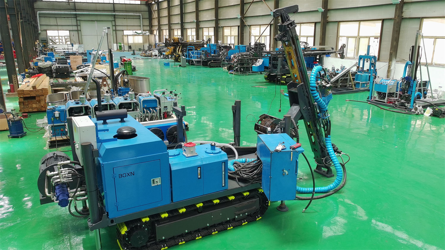
V. Checklist to Confirm Before Procurement for Mountainous Multi-Hole Projects
Site and Access Conditions
- Transport road width, slope, curve radius, bridge and culvert load-bearing capacity, and access road surface conditions.
- Single-hole platform size, distance between platforms, ground load-bearing capacity, and slope drainage conditions.
- Whether forest roads or mining access roads require additional clearing, and whether crawler travel sections require temporary reinforcement.
Drilling Organization and Formation Conditions
- Planned hole diameter specifications and corresponding drilling depths: which one or combination of BQ 800 m, NQ 600 m, and HQ 300 m.
- Whether the hole deviation requirement falls within the 45°–90° range, and whether a combination of vertical and inclined holes is required.
- Whether the hole will enter fault fracture zones, strongly fractured zones, or loss zones, and the corresponding mud program.
Equipment Matching and On-Site Support
- The engine is a 4BTA3.9 type 3.9 L four-cylinder turbocharged direct injection diesel engine, rated power 97 kW, rated speed 2200 rpm, water-cooled, electrical system 24 V; fuel supply and field maintenance conditions need to be confirmed simultaneously.
- Main pump reference flow 220 L/min, main pump pressure 20 MPa; auxiliary pump reference flow 60 L/min, auxiliary pump pressure 17 MPa; cooling method is air-cooled. The heat dissipation conditions of the air-cooled system in high-temperature or dusty environments should be confirmed with the manufacturer.
- The hydraulic system is equipped with high-pressure filtration to reduce wear on hydraulic pumps, control valves, and actuators caused by contaminants; filter replacement intervals and spare parts availability are service items that should be verified before procurement.
- The complete machine can be equipped with wireless remote control for human-machine separation in some actions; remote control cannot replace on-site safety management. During procurement, the remote control coverage range, applicable actions, and on-site warning and unified command requirements should be clarified.
VI. Judgment Methods to Avoid in Common Configuration Trade-offs
First, do not directly equate the N-size 600 m reference drilling depth with the actual completed hole depth under any formation. This site has listed the three specification reference values of BQ 800 m, NQ 600 m, and HQ 300 m, and clearly states that actual drilling depth is affected by multiple factors.
Second, do not simply convert the folding mast and crawler chassis into fixed time savings. These two configurations affect transport status, on-site assembly workload, and hole-to-hole movement method. The specific benefits depend on roads, platforms, and hole layout, and this site does not provide efficiency values that can be directly cited.
Third, do not extend the configuration of one model to the entire series. The CR600I and CR800I both belong to integrated core drill rigs, but their models, drilling depth positioning, and parameters are independent. In procurement documents, they should be listed item by item according to the specific model.
VII. Matters Requiring Further Confirmation
As of the existing information on this site, data such as the CR600I transport dimensions, climbing ability, travel speed, overall weight, fuel consumption, specific matching calibration of the mud pump and engine, applicable altitude, and high/low temperature boundaries are not listed in this site's product information. The above content cannot be supplemented by experience; written information should be requested from the manufacturer before procurement and compared item by item with the project's measured roads, platforms, and formation conditions.
For mountainous multi-hole core drilling projects, the confirmed facts that can be discussed for the CR600I are concentrated in the integrated crawler structure, folding mast, 1.9 m feed stroke, 960 N·m power head, 800 m rope capacity wireline hoist, 127 mm clamp, 45°–90° drilling angle, and BQ/NQ/HQ three specification reference drilling depths. Efficiency calculation should be carried out around these verifiable configurations, and links lacking basis should be clearly marked as pending confirmation, rather than giving seemingly precise construction period or cost conclusions.