












Compressing the requirements of medium-depth mineral exploration for coring equipment into a single question—'Is the drilling depth sufficient?'—usually leads to problems emerging mid-construction. Drilling depth is only one category of condition; the others are distributed across different stages of work: the coring method determines auxiliary time and sample integrity, the hole inclination angle determines whether the equipment can penetrate along the orebody direction, and site conditions determine whether the equipment can access the site and move frequently between locations. Using the published parameters of the CR600I on this site (a 600-meter-class fully hydraulic integrated crawler core drilling rig) as a reference, this article breaks down these conditions item by item to see which can be verified in the parameter table and which must be confirmed separately at the project level.
First, let us clarify what the medium-depth range means. It is defined according to the model hierarchy given in this site's information: the CR600I is positioned around a reference drilling depth of 600 m for N size, while also accommodating 800 m for B size and 300 m for H size. Another tier listed alongside it in the information is the 800-meter-class integrated core drilling rig. In other words, medium-depth projects lie between shallow-hole reconnaissance and deep extension validation. The number of boreholes is often relatively large, while the depth of a single hole does not yet require a larger overall machine investment.
Condition 1: Drilling capability must be verified by size, not just by a single depth figure
The CR600I's drilling capability is stated in the information as 800 m for B size, 600 m for N size, and 300 m for H size. The reason three depth values appear for the same machine is that the three sizes correspond to different drill rods and coring systems, so drilling depth is not a fixed value. The depth requirements of medium-depth projects are usually determined by orebody burial depth and validation objectives. Therefore, when verifying, one should not simply compare the number 600; instead, one must first clarify which size the hole uses and whether the reference drilling depth for that size covers the designed hole depth.
The information also states that the actually achievable drilling depth is further affected by factors such as drilling angle, rock integrity, drill rod weight, downhole tools, mud performance, borehole wall stability, and operating methods. These factors together determine whether the reference value is an upper limit or a level that can be stably achieved. The specific trade-offs need to be confirmed separately in light of the project's strata conditions.
Condition 2: The coring method affects auxiliary time and sample quality
The CR600I is equipped with wireline coring. The wireline hoist system has a 6 mm wire rope, a rope capacity of 800 m, a lifting force of 11 kN, and a lifting speed of 98 m/min. The feature of wireline coring is that the inner tube and core can be recovered without frequently pulling the entire drill string, reducing auxiliary time. The information lists this as a configuration suitable for continuous coring operations in medium-deep holes.
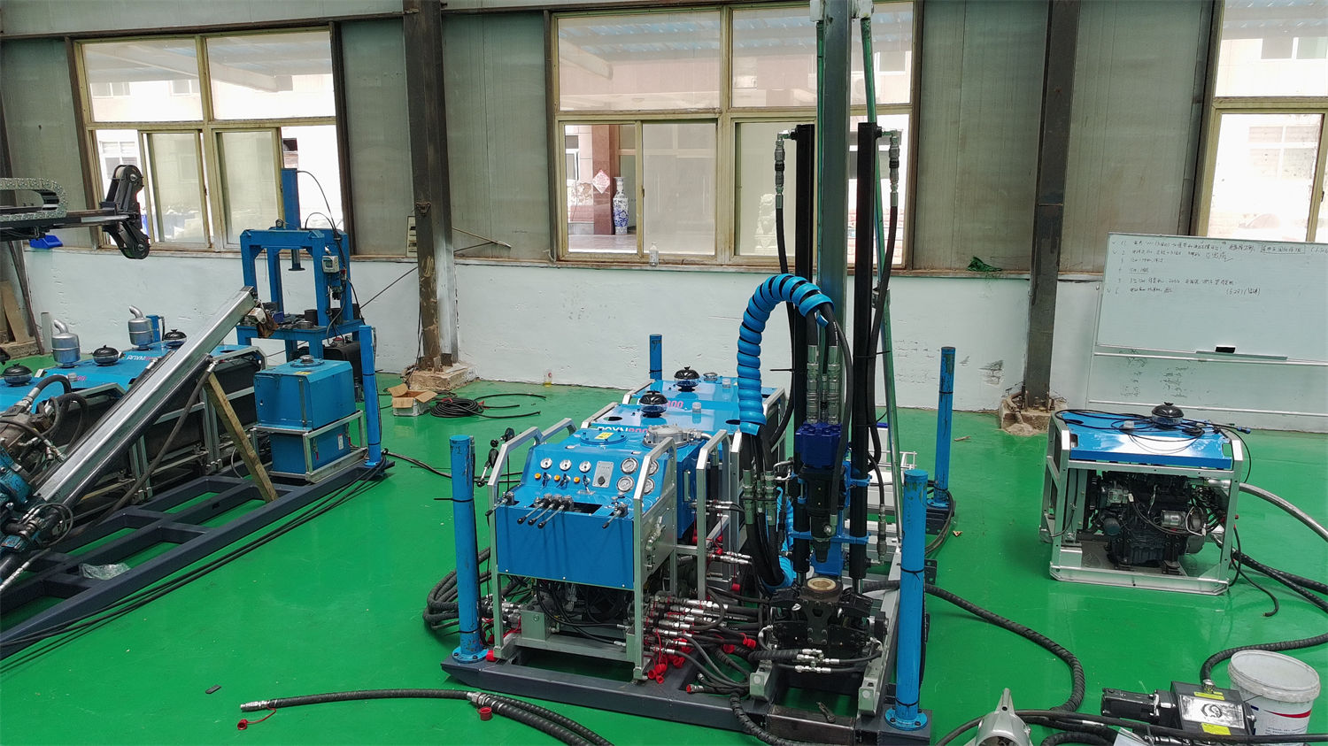
Medium-depth projects often arrange multiple boreholes in the same mining area, and the auxiliary time per hole is repeatedly accumulated with the number of holes. When verifying such conditions, the rope capacity must be compared with the designed hole depth to confirm whether the hoist system's rope capacity covers that hole depth, and whether the downhole drilling assembly is consistent with the selected size system. Core quality also depends on the matching of rotation speed, bit, feed force, and mud parameters. These parameters are given as ranges in the information, and the specific values are not determined within the equipment information.
| Coring-related configuration | Published value | Purpose during verification |
|---|---|---|
| Wireline hoist wire rope | 6 mm | Confirm compatibility with inner tube fishing tools |
| Rope capacity | 800 m | Compare with designed hole depth to see if sufficient |
| Lifting force | 11 kN | Load condition when recovering inner tube and core |
| Lifting speed | 98 m/min | Affects cycle time per coring run |
Condition 3: Inclination adaptability is determined by orebody attitude
The CR600I supports drilling within a 45°–90° range and can drill vertical and inclined holes. For inclined orebodies, vein-type orebodies, fault structures, alteration zones, and concealed orebodies, the information states that reasonably selecting the hole inclination angle can increase the probability of penetrating the target and avoid the drilling direction being too parallel to the orebody strike, which would reduce the effective mineralized length encountered.
Therefore, the inclination condition is not satisfied unilaterally by the equipment, but by the match between equipment capability and orebody attitude. In the infill drilling and orebody boundary validation stages of medium-depth projects, multiple holes at different angles are often needed along exploration lines. When verifying, one must confirm whether the designed angle falls within the 45°–90° range and whether the platform layout can support collar operations at that angle.
The power head has a maximum torque of 960 N·m and a maximum rotation speed of 1150 rpm, and supports hydraulic side shift. Higher rotation speeds are suitable for diamond core drilling, and the side shift function provides working space for drill rod assembly and disassembly, collar operations, and coring tool handling. These configurations are related to collar operations during inclined drilling, but the information does not give differences in torque or rotation speed values at different angles. This part needs to be confirmed separately in combination with actual strata conditions.
Condition 4: Hole depth determines drill rod load, and lifting and feed parameters must keep up
The closer a medium-depth hole is to the machine's reference upper limit, the greater the self-weight of the drill string. The CR600I has a feed stroke of 1.9 m, can handle 1.5 m drill rods, has a feed force of 42 kN and a pull-up force of 130 kN. The mast is a folding structure, and the feed speed supports fast and slow adjustment.
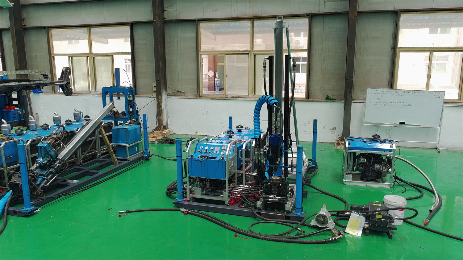
The item to verify for pull-up force is the tripping process, not normal drilling. As hole depth increases, the drill string weight and downhole friction together constitute the load required for pull-up. To judge whether 130 kN is sufficient, the intended drill rod size, hole depth, and downhole conditions must be brought into the calculation. The information itself does not provide a numerical conclusion derived from hole depth.
The chuck has a through-hole diameter of 127 mm and can accommodate common drill rod systems such as NQ, HQ, PQ, NTW, and HTW. It uses hydraulic clamping combined with a wedge-type self-weight anti-drop structure. The choice of drill rod system simultaneously affects coring size and drilling depth judgment, and is an item that needs to be settled in advance in medium-depth projects.
Condition 5: Site and relocation capability are project-level conditions
The CR600I is a fully hydraulic integrated crawler structure. The power system, hydraulic system, power head, mast and feed mechanism, chuck, wireline hoist, mud circulation system, and crawler travel mechanism are integrated on the same platform. The information states that this structure reduces the workload of on-site assembly and repeated connections of split equipment, making it more suitable for exploration projects in mining areas, mountains, hills, forest roads, and locations requiring frequent relocation.
However, integrated does not mean it can directly enter any site. In the site-related section, the information states that before construction, key assessments should be made of transport road width, slope, curve radius, bridge and culvert load-bearing capacity, platform dimensions, ground bearing capacity, and drainage conditions. For sloping-ground operations, the platform should first be leveled and reliable supports should be installed; equipment stability must not be maintained solely by friction between the tracks and the ground. These items are conditions that must be fulfilled before entering the site and cannot be replaced by judgments from the parameter table.
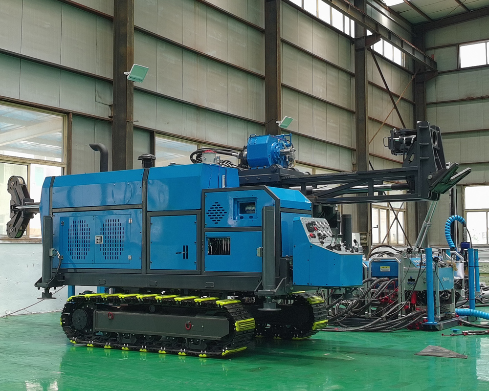
The overall machine power is a 4BTA3.9 type 3.9 L four-cylinder turbocharged direct-injection diesel engine, with a rated power of 97 kW, a rated speed of 2200 rpm, water cooling, and a 24 V electrical system. The power configuration needs to simultaneously satisfy the coordinated operation of the power head, hydraulic system, crawler travel, and mud system. The information maps this to medium-deep hole coring operations under continuous field construction and complex working conditions. The main pump reference flow is 220 L/min and main pump pressure is 20 MPa; the auxiliary pump reference flow is 60 L/min and auxiliary pump pressure is 17 MPa; cooling is air-cooled. The equipment is configured with high-pressure filtration to reduce wear on hydraulic pumps, control valves, and actuators caused by contaminants in the hydraulic oil. These values describe the overall machine's power and hydraulic capability and have no direct conversion relationship with site conditions, so they should not be used to infer whether a certain type of terrain can be entered.
The mud circulation system has a reference flow of 100 L/min, pressure of 7 MPa, rotation speed of 360 rpm, and power of 14 kW. The information points out that in core drilling, mud circulation serves to cool the bit, carry rock cuttings, stabilize the borehole wall, lubricate the drilling tools, and improve the downhole environment. After entering fractured zones, strongly weathered layers, fissure zones, or loss zones, mud viscosity, flow rate, and wall-protection measures should be adjusted according to the return slurry situation. Medium-depth projects commonly encounter fault fracture zones and fissured strata. The handling of this part depends on on-site judgment, and the information does not provide specific mix ratios or operating values.
Putting these conditions into a verification sequence
The requirements of medium-depth mineral exploration for coring equipment can be ordered by judgment sequence as follows: first determine the size system to be used according to the designed hole depth, then confirm whether the coring method and hoist rope capacity can cover that hole depth; next, confirm according to orebody attitude whether the hole inclination angle is within the equipment's supported range; then use the intended drill rods and hole depth to calculate the pull-up force margin; finally, return to the project level to fulfill transport roads, platform dimensions, ground bearing, and drainage conditions.
It is necessary to distinguish that the first four items can be directly compared with corresponding values found in the published CR600I information; the last item belongs to site conditions and must be confirmed in combination with the actual project situation. Content not appearing in the information includes: values beyond the rated drilling depth under different sizes, recommended drilling parameter values given by strata, conclusions on the applicability of transport dimensions to specific roads, and quantitative results for core quality or operating efficiency. These need to be separately verified with the manufacturer or project party during the selection and site-entry stages, and this article does not infer them.