












In the RC500-CS3 documentation, the CS3 three-in-one cyclone sampling system is sometimes broken down into three terms placed together: cyclone, splitting, and bagging. These three stages are not three parallel functional items, but three sequential processes that the same return sample material passes through. Read separately, it is easy to interpret "splitting" as an independent device and "bagging" as a mere process conclusion; read as a continuous sequence, one can see that what this system changes is the path of the sample after it returns to the surface from the inner tube of the drill rod.
This article discusses the sequential relationship and respective meanings of these three stages based solely on published documentation for this model, and does not involve sampling configurations of other models.
First, lay out the order of the three stages
According to the documentation, cuttings generated by reverse circulation drilling return to the surface through the inner tube of the dual-wall RC drill rod, then enter the cyclone system, where high-speed airflow and solid particles are separated, then pass through the splitting mechanism to form samples usable for geological logging and assay, and finally enter the sample collection stage. The three actions are linked in the material flow direction: the cyclone handles gas-solid separation, splitting turns a batch of material into usable samples, and bagging fixes the samples into objects that can be labeled, sent for assay, and archived.
If one reads only "cyclone," one might think it is a dust removal or discharge device; if one reads only "splitting," one might think precision is determined solely by the mechanism; if one reads only "bagging," one might think this stage is just manual labor. Only by reading the three stages together can one see that the output of each stage is the input of the next.
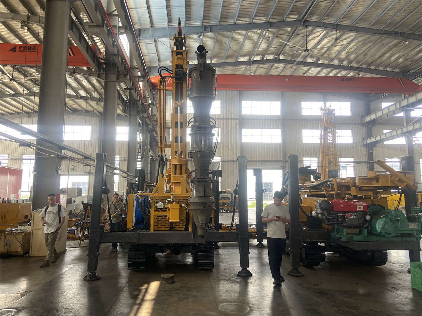
The cyclone stage: first solve gas-solid separation
The documentation states the role of the cyclone very directly—separation of high-speed airflow and solid particles. The return sample material is in a gas-solid mixed state inside the inner tube, with unstable velocity and solids content, and it is meaningless to send it directly to the splitting stage. The task of the cyclone stage is to first separate the airflow from the cuttings, so that subsequent stages face relatively controllable solid material.
This stage itself does not perform deep isolation. The cyclone separates the gas and solids entering at the same moment; it does not record or distinguish which hole section this batch of material comes from. Depth information is added later during bagging and labeling.
The splitting stage: turning return sample into "sample"
The documentation uses the wording "the splitting mechanism forms samples usable for geological logging and assay." Two points in this sentence deserve attention. First, "splitting" means taking a representative portion from the total return sample, not bagging all cuttings; second, the product of this step is already defined as a sample, that is, an object that will subsequently correspond to a specific depth and enter the logging and assay process.
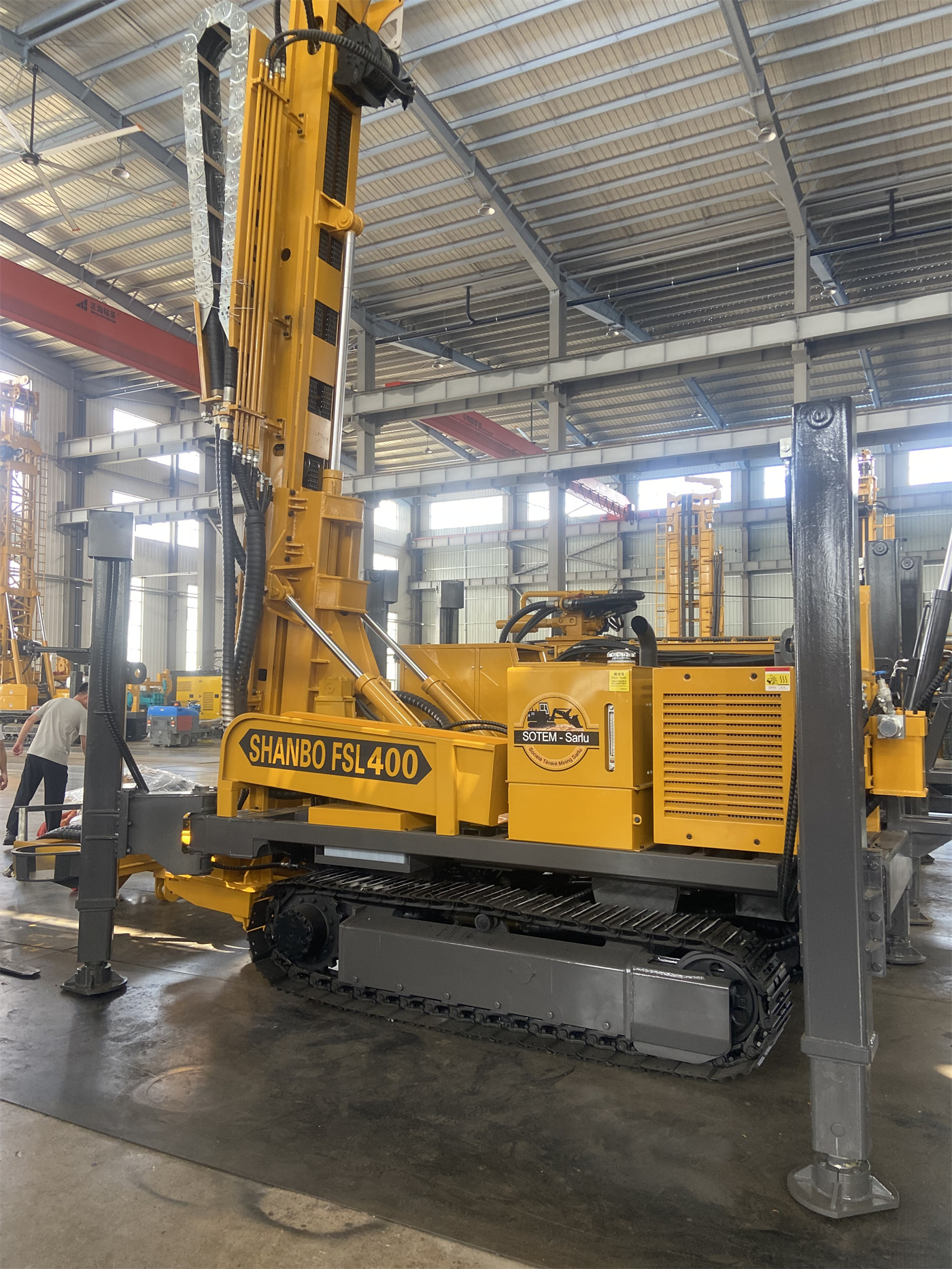
Values such as splitting precision, reduction ratio, and single sample weight are not given in the public documentation. If a project has clear requirements for the splitting ratio, this item needs to be verified with the manufacturer and cannot be directly inferred from the phrase "representative splitting."
The bagging stage: fixing the sample as a traceable object
In this part, the documentation gives management actions rather than mechanical actions: each sample bag can be labeled with hole number, start and end depth, date, and sample number, facilitating assay submission, archiving, and traceability. In other words, bagging is the only one of the three stages that writes "depth" into the sample.
This also explains why the three stages should be read together: cyclone and splitting handle material, while bagging handles material plus information. No matter how smoothly the first two stages are performed, if the labeling in the third stage does not correspond one-to-one, the sample still cannot be restored to hole depth during the assay stage.
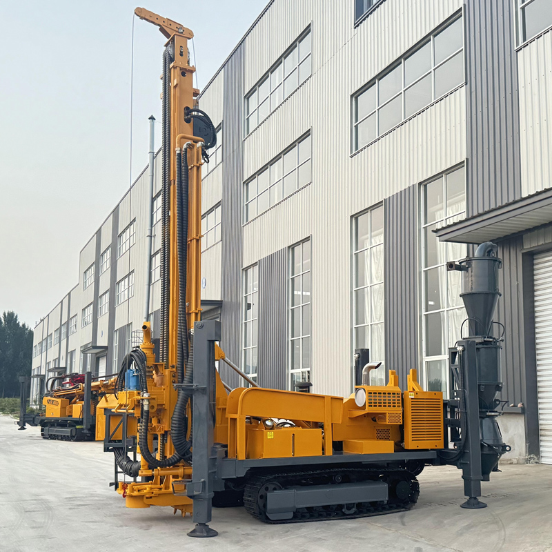
When reading the three stages together, which judgments cannot be made from these three stages
- It cannot be concluded that "samples will not be cross-contaminated." The documentation's description of reverse circulation inner tube return is that it shortens the path of contact between the sample and other formations on the hole wall, helping reduce the probability of cuttings from different depths mixing with each other, while also clearly stating that the final sample representativeness is still related to hole cleaning, rod connection, return sample stability, and on-site sampling management.
- It cannot be concluded that "the splitting ratio is fixed." The documentation does not give the reduction ratio or single sample weight.
- It cannot be concluded that "bagging is completed automatically." The documentation only states what information can be labeled on the sample bag, without explaining who performs the labeling or in what manner.
- It cannot be concluded that "the three stages apply to all formations." The documentation also states elsewhere: in fault fracture zones, breccia, and fractured formations, wall collapse blocks may temporarily remain in the hole and then return concentratedly, thereby affecting the correspondence between samples and depth.
Beyond the three stages, the cleaning points specified in the documentation
In the sampling management section, the documentation mentions that when resuming drilling after rod connection, hole cleaning, or stopping drilling, transition samples should be handled according to on-site sampling procedures to avoid mixing residual cuttings from the previous hole section into samples from the next depth. The locations pointed to by this statement are precisely the connection points between the three stages: the passage between cyclone and splitting, and the container between splitting and bagging. The three-in-one system reduces manual sample pouring and secondary transfer, but cleaning these connection points still falls under on-site sampling procedures.
Other relevant values for RC500-CS3, for reference
| Item | Documented Value |
|---|---|
| Maximum drilling depth | 500 m |
| Hole diameter | 105–400 mm |
| Working angle | 45° / 90° |
| Lifting force | 25 T |
| Axial pressure | 7 T |
| Maximum rotary torque | 10000 / 5000 N·m |
| Maximum rotary speed | 75 / 150 r/min |
| Recommended working air pressure | 1.6–6 MPa |
| Recommended air consumption | 16–55 m³/min |
| Engine | 132 kW Cummins |
| Auxiliary winch lifting force | 1.5 T |
| Hydraulic outrigger stroke | 1.6 m |
| Overall weight | Approx. 12 T |
| Dimensions | Approx. 7 × 2.1 × 2.9 m |
What this documentation does not answer
The cyclone's processing capacity and separation particle size, the splitting mechanism's reduction ratio and single sample weight, sample bag specifications, and the time required for switching and cleaning between the three stages do not appear in the existing public documentation. If a project conducts continuous sampling at fixed footage intervals and has clear requirements for sample weight and splitting ratio, each item should be confirmed with the manufacturer during procurement communication, rather than inferred from the term "three-in-one."